Monday, February 7, 2011

Promiscuity is the nRF24L01+'s Duty

by Travis Goodspeed <travis at radiantmachines.com>
extending the work of Thorsten Schröder and Max Moser
of the KeyKeriki v2.0 project.
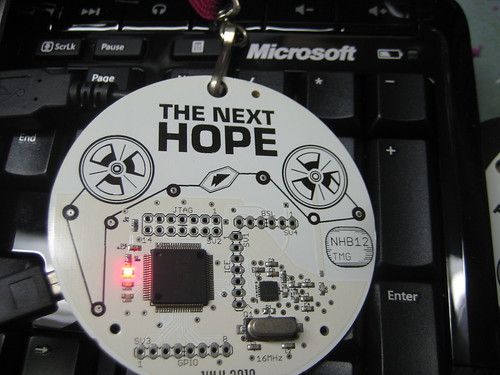
NHBadge and a Keyboard

Similar to Bluetooth, the protocols of the Nordic VLSI nRF24L01+ chip are designed such that the MAC address of a network participant doubles as a SYNC field, making promiscuous sniffing difficult both by configuration and by hardware. In this short article, I present a nifty technique for promiscuously sniffing such radios by (1) limiting the MAC address to 2 bytes, (2) disabling checksums, (3) setting the MAC to be the same as the preamble, and (4) sorting received noise for valid MAC addresses which may later be sniffed explicitly. This method results in a rather high false-positive rate for packet reception as well as a terribly high drop rate, but once a few packets of the same address have been captured, that address can be sniffed directly with normal error rates.

As proof of concept, I present a promiscuous sniffer for the Microsoft Comfort Desktop 5000 and similar 2.4GHz wireless keyboards. This vulnerability was previously documented at CanSecWest by Thorsten Schröder and Max Moser, and an exploit has been available since then as part of the KeyKeriki v2.0 project. My implementation differs in that it runs with a single radio and a low-end microcontroller, rather than requiring two radios and a high-end microcontroller. My target hardware is the conference badge that I designed for the Next Hope, running the GoodFET Firmware.

Part 1: or, Why sniffing is hard.
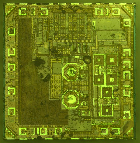
nRF24L01 Die

Radio packets usually begin with a preamble, followed by a SYNC field. In the SimpliciTI protocol, the SYNC is 0xD391, so the radio packets will begin with {0xAA,0xD3,0xD91} or {0x55,0xD3,0x91}. The AA or 55 in the beginning is a preamble, which is almost universally a byte of alternating 1's and 0's to note that a packet is beginning, followed by the SYNC field which makes sure that the remainder of the packet is byte-aligned.

In the case of the Nordic radios, there is no SYNC pattern unique to the radio. Instead, the MAC address itself serves this purpose. So an OpenBeacon packet will begin with {0x55, 0x01, 0x02, 0x03, 0x02, 0x01} while a Turning Point Clicker's packets will begin with {0x55, 0x12, 0x34, 0x56}. The preamble in this case will be 0x55 if the first bit of the SYNC/MAC is a 0 and 0xAA if the first bit is a 1. To make matters worse, the chip does not allow a MAC shorter than three bytes, so previously it was believed that at least so many bytes of the destination address must be known in order to receive a packet with this chip.

Moser and Schröder solved this problem by using an AMICCOM A7125 chip, which is a low-level 2FSK transceiver, to dump raw bits out to an ARM microcontroller. The ARM has just enough time to sample the radio at 2Mbps, looking for a preamble pattern. If it finds the pattern, it fills the rest of register memory with the remaining bits and then dumps them to the host by USB. In this manner, every prospective MAC address can be found. Once the address is known, KeyKeriki places that address in its second radio, an nRF24L01+, which is used to sniff and inject packets.

A similar solution is used in Michael Ossmann's Project Ubertooth sniffer for Bluetooth. See that project's documentation and Ossmann's Shmoocon 2011 video for a more eloquent explanation of why sniffing without a known SYNC is so hard.

Part 2: or, Sniffing on the cheap.
My trick for sniffing promiscuously involves a few illegal register settings and the expectations of background noise. You can find code for this in the AutoTuner() class of the goodfet.nrf client.

First, the length of the address to sniff must be reduced to its absolute minimum. The datasheet claims that the lowest two bits of register 0x03 are responsible for address width, and that the only valid lengths at 3 bytes (01b), 4 bytes (10b), or 5 bytes (11b). Setting this value to 00b gives a 2 byte match, but when checksums are disabled, this results in a deluge of false-positive packets that appear out of background noise.
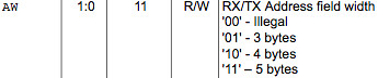
nRF Address Width

Second, it is necessary to begin receiving before the SYNC field appears, as the Nordic chips drop the address of incoming packets, leaving only the payload. By looking at the noise returned when the address is at its shortest length, it is clear that background noise includes a lot of 0x00 and 0xFF packets as well as 0xAA and 0x55 packets, which are likely feedback from an internal clock. What then would happen if the address were to be 0x00AA or 0x0055?

What happens is that noise activates the radio a bit early, which then syncs to the real preamble, leaving the SYNC field as the beginning of the packet payload! This is because the preamble and SYNC do not need to be immediately adjacent; rather, the SYNC can be delayed for a few bytes from the preamble in order to allow for longer preambles in noisy environments.

As a concrete example, an OpenBeacon packet looks something like the following. The SYNC field is 0x0102030201, so the packet will be cropped from that point backward. 0xBEEF is all that will be returned to the application, with everything prior to that cropped.
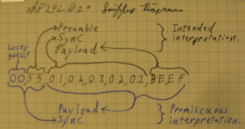
nRF24L01+ Promiscuous Mode

By making the address be 0x0055 and disabling checksums, that same packet will sometimes be interpreted as shown on the bottom. The preamble will be mistaken for a SYNC, causing the real SYNC value to be returned as the beginning of the payload. In that way, I am able to determine the SYNC/MAC field without any prior knowledge or brute force exploration.

This does depend upon the preamble being preceded by 0x00, which occurs often in background noise but is not broadcast by the attacker. So the odds of receiving a packet, while significantly worse than we'd like, are much better than the 1/2^16 you might assume. In experiments, one in twenty or so real packets arrive while a significant number of false positives also sneak in.

Recalling that the MAC addresses are three to five bytes long, and that radio noise is rather distinct, it stands to reason that noise can easily by separated from real packets by either manually checksumming to determine packet correctness or simply counting the occurrences of each address and taking the most popular. You will find an example log of OpenBeacon packets and false positives at http://pastebin.com/8CbxHzJ9. Sorting the list reveals that the MAC address 0x0102030201 is the most popular, which is in fact the address used by OpenBeacon tags.

Rather than rely on packet dumps and sorts, there is an autotune script that identifies network participants and prints their MAC addresses. Simply run 'goodfet.nrf autotune | tee autotune.txt' and go out for a coffee break while your device is transmitting. When you come back, you'll find logs like the following, which has identified a nearby OpenBeacon transmitter.
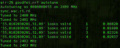
goodfet.nrf autotune

As low data-rate devices require significantly more time than high-rate devices to identify, such devices will either require undue amounts of patience or a real KeyKeriki. In the case of a Nike+ foot pod, I'm resorting to using loud hip hop music to trigger the sensor, which is left inside a pair of headphones. My labmates are not amused, but it is a great way to reveal the radio settings when syringe probes aren't convenient.

Part 3: or, Sniffing a keyboard effectively.

Having a class to identify channels and MAC addresses is most of the problem, but there are remaining issues. First, the packets themselves are encrypted, and that cryptography must be broken.

Fear not! We won't need to do any fancy math to break this cryptography, as the key is included at least once in every packet. Moser and Schröder's slides explain that the packet's header is cleartext, while the payload is XOR encrypted with the MAC address.
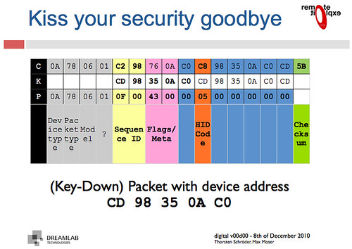
XOR Crypto!

Applying an XOR to the proper region yields decrypted packets such as the following. Because these contain USB HID events, key-up HID events quite often include long strings of 0x00 bytes. When XOR'ed with the key, those zeroes produce the key, so some packets contain the XOR key not just once, but twice!
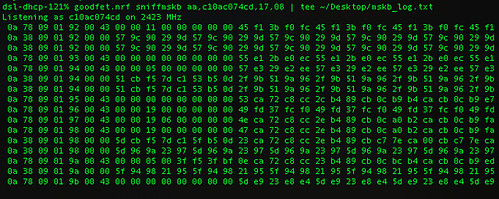
MSKB5k Traffic

Finally, the USB HID events need to be deciphered to get key positions. Mapping a few of these yields meaningful text, with bytes duplicated in the case of retransmissions and omitted in the case of lost packets. Disabling checksums will allow the dropped packets to be converted to a smaller number of byte errors, while tracking sequence numbers will prevent retransmitted keys from being displayed twice. Regardless, the results are quite neighborly, as you can make out the sentence typed below in its packet capture.
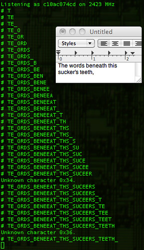
NHBadge Key Sniffer

Part 4; or, Reproducing these results.

All of the code for this article is available in the GoodFET Project's repository, as part of GoodFETNRF.py and its goodfet.nrf client script. The hardware used was an NHBadge12, although an NHBadge12B or a GoodFET with the SparkFun nRF24L01+ Transceiver Module will work just as well.

To identify a nearby Nordic transmitter, run 'goodfet.nrf autotune'. Keyboards can be identified and sniffed with 'goodfet.nrf sniffmskb', while a known keyboard can be sniffed and decoded by providing its address as an argument, 'goodfet.nrf sniffmskb aa,c10ac074cd,17,09'. The channel--0x17 in this case--will change for collision avoidance, but channel hopping is slow and resets to the same starting channel. Identification of the broadcast channel is faster when the receiver is not plugged in, as that causes the keyboard to continuously rebroadcast a keypress for a few seconds.

All code presently in the repository will be refactored and rewritten, so revert to revision 885 or check the documentation for any changes.

Conclusions

Contrary to prior belief, the nRF24L01+ can be used to promiscuously sniff compatible radios, allowing for keyboard sniffing without special hardware. It's also handy for figuring out the lower levels of the otherwise-documented ANT+ protocol, and for reverse engineering vendor-proprietary protocols such as Nike+.

Additionally, it should be emphasized that the security of the Microsoft keyboards in this family is irreparably broken, and has been since Moser and Schröder published the vulnerability at CanSecWest. (It's a shame, because the keyboards are quite nicer than most Bluetooth ones, both in pairing delay and in battery life.) Do not purchase these things unless you want to broadcast every keystroke.

While I have not yet written code for injecting new keystrokes, such code does exist in the KeyKeriki repository and would not be difficult to port. Perhaps it would be fun to build stand-alone firmware for the Next Hope badge that sniffs for keyboards, broadcasting Rick Astley lyrics into any that it finds?

Please, for the love of the gods, use proper cryptography and double-check the security your designs. Then triple-check them. There is no excuse for such vulnerable garbage as these keyboards to be sold with neither decent security nor a word of warning.

Monday, January 24, 2011

Generic CC1110 Sniffing, Shellcode, and iClickers

Chipcon CC1110 Logo

Howdy y'all,

I haven't the time to write individual posts on these subjects, but I do have plenty of new features for the CC1110 that are worth sharing. Rather than explain how they were written in too much detail, I invite you to read the source code, which is mostly Python and C shellcode.
In order to follow along with these examples, you will need to have SmartRF Studio installed to /opt/smatrf7. While this requirement will go away in a few weeks, the GoodFET client temporarily needs SmartRF Studio for machine documentation about the CC1110. You can find more details on SmartRF requirements in the goodfet.cc client page.

(1) Packet sniffing, and other neighborly scripts.

GoodFETCC now has packet sniffing support for the SimpliciTI protocol used by the Chronos watch. Not only that, but it implements the protocol well enough to act as an access point for the watch, collecting accelerometer data and deciphering it for the host.
GoodFET Simpliciti Sniffing!

Run an access point with 'goodfet.cc simpliciti [band]'. (This command will likely change names soon, as it is a rather ugly hack which only supports the Chronos accelerometer feature.) The optional parameter should be us, eu, or lf for the American, European, and Low Frequency versions of the watch.
GoodFET SimpliciTI Client

Not only protocols intended for the GoodFET, but also others which are coincidentally compatible, are supported. Thanks to some register settings contributed by Mike Ossman, you can sniff and decipher i<clicker traffic with 'goodfet.cc iclicker'.
goodfet.cc iclicker

The i<clicker uses a Xemics XE1203F (PDF) radio chip, shown below. The XE1203F is nearly as configurable as the CC11xx parts, except that it is limited to 2FSK encoding. Previously, this protocol could be sniffed with the GR-Clicker project and a USRP, but the highly-versatile CC1110 chip allows this to be done with neither a software defined radio nor a chip identical to that used by the transmitter.
iClicker

If you find it handy to see when a device is broadcasting, you can produce an ASCII-art plot of signal strength with 'goodfet.cc rssi [freq]':
GoodFET CC1110 RSSI Graph

Care to jam another transmitter? Just like with the Next Hope Badge's GoodFET mode, it takes a single command to hold a carrier wave.
'goodfet.cc carrier [freq]'
Chipcon Carrier

(2) Shellcode, now for quiche-eaters!

At the risk of appearing to facilitate quiche-eating, I'd like to quickly explain the new shellcode interface for placing code fragments on a Chipcon 8051 target, such as the CC1110.

The Chipcon radios have certain functions which are timing sensitive, chief among these being the rewriting of flash memory and the use of the digital radio core. If flash memory is not pulsed with the correct timing, mis-writes will occur. If the radio is read too slowly, bytes will be missed and a buffer underflow will ruin the transaction. Similarly, a transmission might fail if the single-byte transmission buffer isn't refilled quickly enough. I've also had trouble, for reasons that I can poorly explain, configuring the crystal oscillator through the debugging interface without shellcode.

As I described in my CC2430 Debugging Notes, the recommended method of flashing memory is to write a small block of code into XDATA RAM which does the actual write, then to branch to this code, waiting for a HALT (0xA5) opcode to return control to the debugger. This routine is provided in SWRA124 as machine code with assembly comments, beginning with the fragment shown below.
CC2430 Flash Routine

While this is fine and dandy for code that works, it's a bit infuriating to debug code in machine language. (Is that opcode supposed to be 0xA5 or 0xA6? Is the length of this instruction correct? Similar frustration abounds.) To correct for this, the GoodFET project now has a trunk/shellcode directory in addition to trunk/firmware and trunk/client. Shellcode is compiled for target microcontrollers, in this case just the CC1110 by SDCC, the Small Device C Compiler.

For example, this is the code that used to configure the crystal oscillator on the CC1110, a prerequisite for any radio operations:
Chipcon Shellcode

That ugly mess becomes the following little fragment of C. It is compiled by 'sdcc --code-loc 0xF000 crystal.c' in order to place the code squarely within RAM, which is executable in this 8051 clone's unified memory architecture. (It's a Harvard chip that acts Von Neumann, or the other way around.)
CC1110 Crystal Shellcode

For inputs to these functions, and also for their return values, I find it more convenient to declare arrays at known locations than to read the symbol files to find them. The syntax for placing an array in XDATA memory at 0xFE00 is 'char __xdata at 0xfe00 packet[256];'. You can find examples of this in txpacket.c and rxpacket.c in the GoodFET repository.

(3) Care to join the fun?

There are a number of features remaining to be implemented in shellcode. Among them in a completed port of Ossmann's $15 Spectrum Analyzer, which I began in CC1110 Instrumentation in Python and you can find in the contrib/ directory of the GoodFET repository. By dropping the GUI interface and replacing it with timing delays, full spectrum scans can be made in decent time without requiring that anything in flash memory be changed.

Another handy tool would be an OOK sniffer that over-samples, using the infinite-packet-length trick described in the CC1110 datasheet to fill ram with a recording. Triggering on RSSI allows the beginning of the packet to be reliably timed, with oversampling allowing for correction on all later bits. I've begun to implement this as 'goodfet.cc sniffook [freq]', but an enterprising neighbor should be able to start sniffing garage door remotes in short order.
A Morse-code library in combination with an external amplifier would also be neighborly for the licensed amateur bands. The ability of the microcontroller to quickly return and channel hop might be able to account for, among other things, the Doppler shift experienced in EME moon-bounce experiments, without losing backward compatibility with 19th century radio technology.

As a prize, I offer one ale apiece for GoodFET patches implementing these features.

Stay neighborly,
--Travis Goodspeed
<travis at radiantmachines.com>

Monday, December 6, 2010

Hacking a Knitting Machine's Keypad

by Travis Goodspeed <travis at radiantmachines.com>
in collaboration with Fabienne Serriere and Arjan Scherpenisse,
at Mediamatic's RFID Devcamp 2010, Amsterdam,
for Multithreaded Banjo Dinosaur Knitting Adventure 2D Extreme,
with kind thanks to David Carne.

Multi-Threaded Banjo Dinosaur Knitting Adventure 2D Extreme

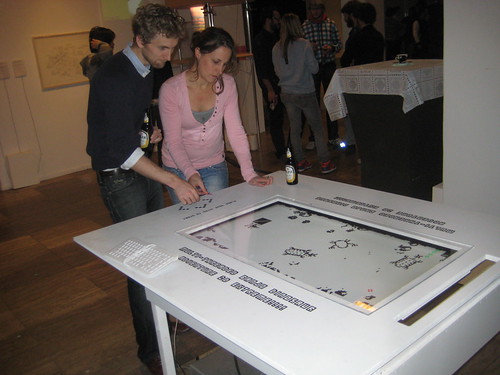
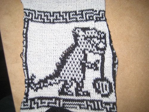
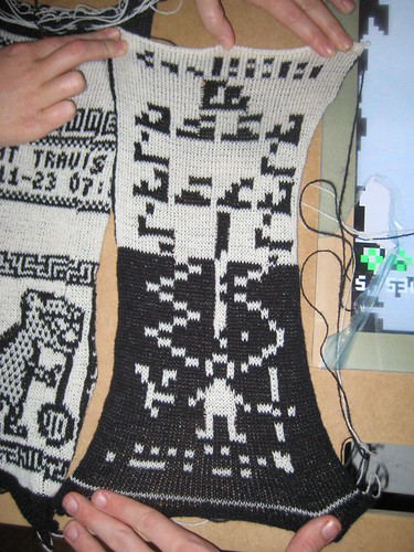
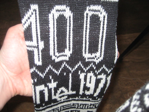
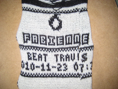
Thanks to some extra-neighborly blackmail by Fabienne, I spent last week hacking up a storm in Amsterdam. By extending the work of Steven Conklin, Limor Fried, and Becky Stern, we were able to hack a Brother KH930 knitting machine to print high score panes from a custom video game in yarn. This game was then displayed at Mediamatic for SensorFest, leading all sorts of neighbors to learn that RFID, socializing, and beer can lead to a neighborly time. Never in my life did I expect to get such an adrenaline rush from knitting, much less from from this newfangled social networking nonsense.

Conklin's technique for loading new patterns into the machine involves using an FTDI chip to simulate a Tandy PDD1 floppy disk drive, then typing "CE 5 5 1 STEP 1 STEP CE STEP STEP CE 9 0 3 STEP STEP" to load a new pattern set from disk and print pattern 3 of the set. (551 is the command to read from disk, and patterns held in RAM begin at 900.) For our exhibit, this sequence was far too complicated to type for every half meter of output, so we hacked the device's keypad for scripting.

This article describes how a matrix keypad works, how we reverse engineered the specific keypad of the Brother KH930, and how to use an Arduino with a handful of transistors to automate the typing of commands necessary for loading a new pattern from an emulated floppy disk. It should be applicable to all sorts of keyboards, but for those with serial protocols there might be a simpler method.

Unfortunately, there won't be room here to describe the first emergency knitting machine purchase in history, our A-Team trip to the far side of Holland in a borrowed van, or the case of Club Mate that we begged from a squatter bar in order to finish the project in the five days allotted.


A keypad matrix is most often built with switches that connect a row wire to a column wire. By keeping every column in a high-impedance state with pull-up resistors, then dropping each row low in sequence, the column inputs can be sensed to determine when a button is pressed. Dave's Hacks' first article on IM ME Hacking describes in detail how the keypad of the GirlTech IMME works, and all other implementations seem to function similarly.

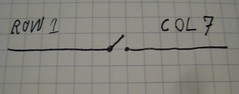
The connections between rows and columns are just switches.
KeySchem

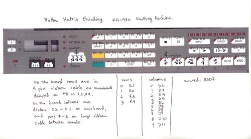
While in a perfect world, rows and columns would be arranged exactly as they appear visually, this is rarely efficient to route in copper for more than twelve buttons. We produced the diagram below by scanning the keyboard membrane, then pushing a button while using the continuity tester to see which row and column wire were connected. The table at the bottom converts from wire signal names to the Arduino signal names used within the client library.
KH930 Keypad Topside


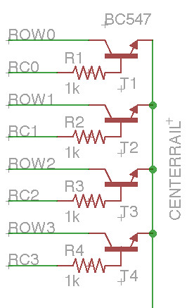
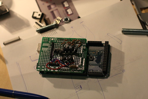
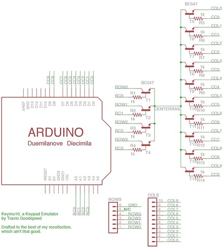
In order to connect rows and columns to a center rail, I used BC547 NPN transistors prototyped on an Arduino shield. Each has a 1K resistor on the base. Row transistors have the collector coming from the row signal and the emitter going to the common rail; column transistors are the same, except that the collector and emitter are swapped in order to fit the direction of current.
Keymu10 Rows

As each transistor conducts when only when its base is high, the Arduino can press a key by first dropping all outputs low, then raising a row control line (RCx) and a column control line (CCx) high. Because of debouncing and a limited scan rate, this must be held for a short amount of time before releasing the key.


Such a design fits perfectly well on a prototyping shield, although the transistors are a tight fit. I recommend first prototyping a single row and column to ensure that the transistors are properly aligned, as current direction might be different on your keypad.
Keymu Prototype

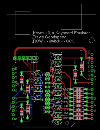
For those who prefer to have a board fabbed, here's a proper schematic and layout. Gerbers and Eagle CAD source files are available in the project's subversion repository.
Keymu10 Schematic
Keymu10 Shield


A more sophisticated software implementation would involve using the Arduino's serial port to communicate with the host, accepting strings in ASCII and translating them to keypresses. We decided against such a complication because we feared relying on a second long USB cable. Further, we thought it handy when necessary to be able to run the device stand-alone with a single (reset) button press from the operator signaling that the next pattern should be loaded.

Full keyboard emulator code is available either by pastebin or from SVN. You'll find it in banjo/code/arduino.
svn checkout svn://svn.mediamatic.nl/devcamps/camp10/banjo

The code works by using simple methods to press a row and column by raising those pin voltages. Higher level methods allow for such functions as loading a pattern from disk or printing a pattern, each by performing multiple key presses and occasionally inserting a delay. By placing this within the Arduino code's setup() function, the pattern is loaded whenever the device is reset.

New patterns are loaded from the Banjo Dinosaur Knitting Adventure 2D Extreme game by first starting a floppy disk emulator--as per Steve Conklin's technique--then pulsing the DTR line of the arduino in order to cause a reset. The Perl for that is just a single line,
Device::SerialPort->new("/dev/ttyACM0")->pulse_dtr_on(100)

The end result, with a machine typing by itself, looks a little like this,


That's all there is to it. With fourteen transistors and just as many resistors, you can script your knitting machine--or any other keypad device--from a microcontroller without modifying the underlying firmware.

As a final note, I will give a cookie to the first neighbor who uses this technique to dump all of the power codes from a universal infrared remote control, or to program something long and sophisticated into a graphing calculator that lacks a link port.

Banjo Dinosaur
Arecibo Pattern
Intel 4001 Art
Multi-Threaded Banjo Dinosaur Knitting Adventure 2D Extreme

Monday, November 1, 2010

Bitmapped Sprites on the GirlTech IMME

by Travis Goodspeed <travis at radiantmachines.com>
with sprites by Eli Skipp,
extending Dave's LCD reversing,
and with thanks to Mike Ossmann.

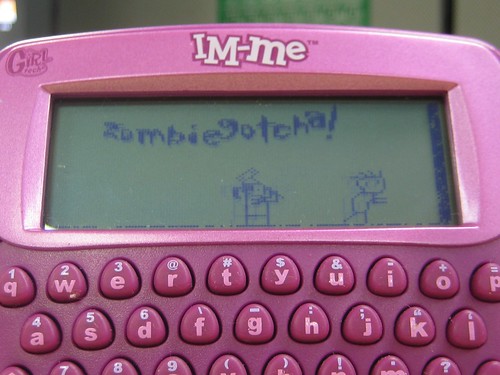
ZombieGotcha

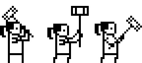
The GirlTech IMME is a fine platform for radio hacking and embedded programming, but the LCD of the device is by no means designed for lightning fast graphics. In this brief article, I demonstrate the method by which a sprite library can be constructed which abstracts away the less neighborly minutia of the LCD in favor of a row-wise framebuffer that gets flushed to the LCD as appropriate. This isn't fast enough for a port of Sonic the Hedgehog, but it's certainly sufficient for ZombieGotcha, a network disease simulation game that Eli Skipp and I are prototyping.

To quickly recap, the GirlTech IMME is a children's toy powered by the CC1110F32, which combines an 8051 microcontroller with a versatile sub-GHz radio. The toy also includes a text LCD controller and keyboard, making it a delightful platform for embedded systems hacking and prototyping. Thanks to Dave's article on attaching a debugger and reversing the LCD, it is possible to wire a GoodFET into the IMME, allowing for debugging and reprogramming of the device.


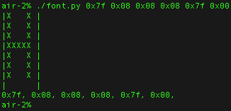
Since the days of the first raster displays, computers have been drawing images as rows, because that's the way that a television's electron stream is traced along the display. The IMME draws rows internally, but because it is intended to draw fonts, its rows are eight pixels tall. For example, the bytes {0x7f, 0x08, 0x08, 0x08, 0x7f, 0x00} are pushed to the LCD in order to draw an uppercase letter H in Dave's LCD Demo for the IMME. Drawing this on graph paper or rendering it by Python, it becomes clear that 0x7F represents a side of the letter, 0x08 represents the bar, and 0x00 is the space following the letter.

IMME Font 'H'

Rather than attempting to natively store a framebuffer in the LCD's format, I chose to internally index by row, then to translate during the export of the framebuffer to the LCD. My primary reason for doing this is to maintain portability of the ZombieGotcha code to custom hardware. It also simplifies the transcription of sprites from original bitmaps to C structures.

Having an internal framebuffer is not without cost, however. The buffer is 132 pixels wide and 64 pixels tall. Even with bit-packing, this is more than a kilobyte in size, consuming more than a quarter of the CC1110's 4kB of XDATA RAM. (Programs and sprites are stored in CODE Flash memory, of which there is 32kB, so this limit is not quite so severe as it sounds.)


girlpix

My sprite toolchain is begun with bitmap images submitted by the artist. I cannot stress enough how important it is that your pixel artist understand pixels. Every sprite must be drawn at native resolution, with proper offsets of each frame and an understanding that the LCD is what it is, regardless of what Photoshop might render.

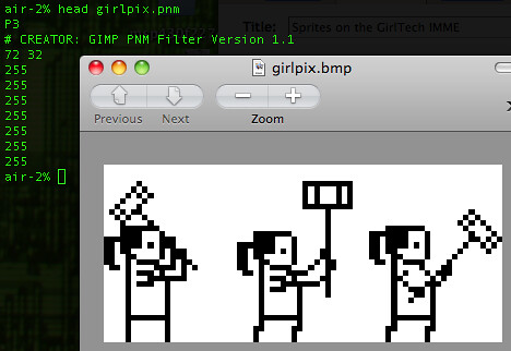
From the original bitmap sprites, PNM files are produced that are more easily parsed by Perl. This format consists of whitespace-delimited words for the format, width, and height of the sprite. In this case, the sprite consists of three frames, each of them being 24 pixels width and 32 pixels tall. Other sizes are possible, of course, but it is convenient for bit packing that the width is an even multiple of 8, so that the old pixels needn't be read back in.

PNM Format

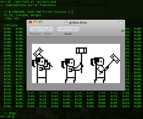
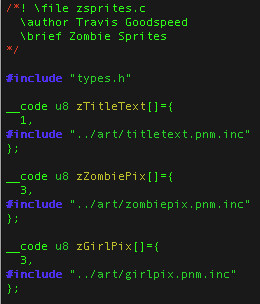
It is then necessary to use an ugly Perl script to convert the sprite from a PNM to a C array of bytes. Pretty Perl won't work, of course, because such a thing doesn't exist. My script, sprite2c.pl, takes a 24-bit color PNM file and converts it to a 1-bit map that is byte-packed. Each of these is included by the preprocessor as a __code unsigned char[], with the __code keyword implying that the object should be stored in Flash rather than RAM.

sprit2cl.pl

Sprite animations are performed by storing the frame count along with the width and height in the C structure. Considering the resource constraints of this system, frame counts change very rarely and are stored within the C code.

zsprites.c


Dumping the frame-buffer to the LCD is as simple as writing every stripe of data to the screen. Potentially, as an optimization, you could keep track of which stripes have been invalidated across what horizontal range, updating only where necessary.

Keeping in mind that the LCD is updated as stripes of 8 pixels in height, code such as the following will refresh the entire LCD from the frame-buffer. Be sure not to erase the LCD between writes, as that would cause unnecessary flickering.

Framebuffer Dump

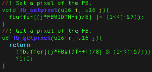
The framebuffer elements themselves are grabbed by selecting the pixel index divided by 8, then masking off the selected bit. The following functions work admirably for this purpose.

FBGetSet

If greater performance is required, a game should certainly be designed with a custom graphics library that optimizes the few things it does most. Performances can be gained by storing sprites and the frame-buffer natively in the row/stripe format that the LCD expects, simplifying conversion. Mike Ossmann used the technique of basing most graphics around vertical lines in his spectrum analyzer firmware, allowing for channels to be redrawned as they are scanned rather than flushed from a frame-buffer.

As the ZombieGotcha game is largely turn-based and the frame-rate is not a dire concern, I don't expect to optimize the sprite library much beyond what is presented here.

One major addition will be that of screenshots, as I'd like to produce animated GIFs of game action for the website. Screenshots can be produced by the method that I outline in CC1110 Instrumentation with Python, dumping the frame-buffer from XDATA with a GoodFET and writing that to disk. Alternatively, full-speed screenshots could be dumped by sniffing the LCD's SPI bus using a Total Phase Beagle or other SPI protocol analyzer.

For those of you with an IMME, Eli and I will be releasing the ZombieGotcha game at the Twenty-Seventh Chaos Communications Congress in Berlin this winter. We'll bring a bed of nails for reflashing IMME units on the spot, as well as GoodFET kits for modifying your IMME to be a development kit. (The ZombieGotcha will also run on full-custom hardware, but we are maintaining IMME support in parallel.)

As a final note, a teaser of the ZombieGotcha opening screen can be found here in the Intel-Hex format. I'll give a GoodFET40 kit to the first neighbor who sends me an animated GIF of it and a script to generate the same, either by a debugger or an emulator.

Tuesday, October 5, 2010

CC1110 Instrumentation with Python

by Travis Goodspeed <travis at radiantmachines.com>
concerning the GirlTech IMME,
utilizing the GoodFET's Chipcon Debugger
to instrument Michael Ossmann's $16 Pocket Spectrum Analyzer.


Kenwood Spectrum, Overlay

Often a neighbor, such as myself, finds himself with a damned useful tool that's missing logging. Further, when this is a black-box application, it is undeniably inconvenient to patch in logging where no communications method exists. In this brief article, I will demonstrate how to instrument a Chipcon CC1110 application using Python and a GoodFET with zero bytes of modification to the original firmware image. My target's source code is available, but the technique applies just as well to black-box firmware.

Specifically, I want to dump the raw data from Michael Ossmann's $16 Pocket Spectrum Analyzer in order to demo it on stage at our Toorcon 12 talk, Real Men Carry Pink Pagers. I'll assume the reader to be familiar with Mike's article, as well as my article on wiring an IMME for debugging with a GoodFET. Readers wishing to play along can order a GoodFET31 for little or no money by following these instructions.

From the datasheet or Mike's Makefile it can be seen that the external RAM (XDATA, which is called external for historic reasons) section begins at 0xF000. The only structure at this location is xdata channel_info chan_table[NUM_CHANNELS], where NUM_CHANNELS is defined to be 132 and the channel_info struct is eight bytes, defined as
typedef struct {
/* frequency setting */
u8 freq2;
u8 freq1;
u8 freq0;

/* frequency calibration */
u8 fscal3;
u8 fscal2;
u8 fscal1;

/* signal strength */
u8 ss;
u8 max;
} channel_info;


The first several entries in this struct might be as follows. The first of these lines defines the frequency to be 0x22af4b, the frequency calibration to be 0xef2c27, and the signal strength to be 0x41. The final byte defines the maximum strength, which is zero unless max-highlighting mode is turned on.
 22 af 4b ef 2c 27 41 00
22 b1 43 ef 2c 27 3e 00
22 b3 3b ef 2c 27 46 00
22 b5 33 ef 2c 27 3c 00
22 b7 2b ef 2c 27 44 00
22 b9 23 ef 2c 28 3c 00
22 bb 1b ef 2c 28 42 00
22 bd 13 ef 2c 28 3f 00
22 bf 0b ef 2c 28 3d 00
22 c1 03 ef 2c 28 40 00
22 c2 fb ef 2c 28 3d 00
22 c4 f3 ef 2c 28 3e 00
...


This information can be extracted by halting and resuming the CPU, just as I did in my article on the PRNG Vulnerability of Z-Stack's ZigBee SEP ECC implementation. That is, GoodFETCC.CCpeekdatabyte() is used to grab these bytes from the CC1110's RAM. The following code dumped the fragment shown above.
#!/usr/bin/env python 

import sys;

sys.path.append('/Users/travis/svn/goodfet/trunk/client/')

from GoodFETCC import GoodFETCC;
from intelhex import IntelHex16bit, IntelHex;
import time;

client=GoodFETCC();
client.serInit();

client.setup();
client.start();

bytescount=8*132;
bytestart=0xf000;

while 1:
time.sleep(1);
client.CChaltcpu();

dump="";
for foo in range(0,bytescount):
dump=("%s %02x" % (dump,client.CCpeekdatabyte(bytestart+foo)));
if foo%8==7: dump=dump+"\n";
print dump;
sys.stdout.flush();
client.CCreleasecpu();


To get proper data, it is necessary to add a wake-up delay of a few seconds, so that the table is populated by the first sampling. Additionally, it is handy to convert the frequency to MHz from its native unit (Hz/396.728515625). Finally, successive pages should be separated by a time column in order to facilitate graphing. The result is this script, which can be found in the GoodFET project as "contrib/ccspecantap/specantap.py".

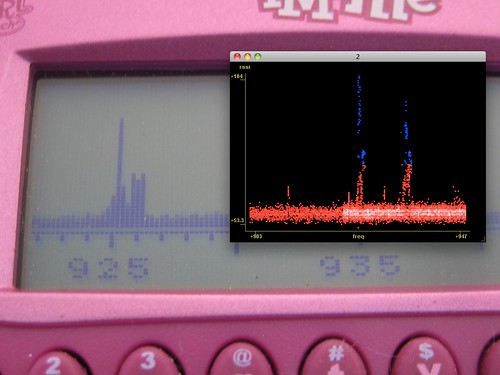
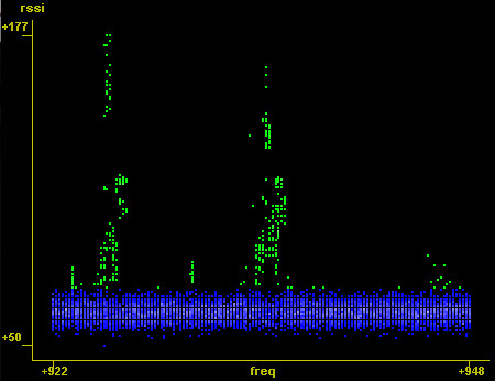
An example recording can be seen below, as a spectrum recording of a friend's Kenwood FreeTalk UBZ-AL14 FM Transceiver unit. This is compatible with other family FM radios, and I wanted to know which center frequencies were in use. In the first image, I've highlighted the noise floor as blue and the peaks as green. In the second image, the time domain is used to show broadcasts on several channels in sequence, all of which fall into one of the two center frequencies: 925MHz and 935MHz. The raw data is here, best viewed with NASA's excellent Viewpoints tool.
Kenwood FreeTalk Spectrum
Kenwood FreeTalk Channels

Future additions to this project will include integration into the GoodFET radio framework, as well as a 2.4GHz version built around the CC2430 and CC2530. The performance of the tap can be greatly improved by using block transactions rather than peeking individual bytes, and the view can be re-tuned by poking the configuration IDATA variables, positions of which are described in specan.rst as produced by the SDCC compiler.

It's also handy to know that a Chipcon radio will halt if the 0xA5 opcode is executed. In this manner, patching a single byte of a while() loop can allow the state at every iteration to be dumped.

This technique of scripted debugging through a programmer can be handy for more than instrumentation. Unit tests can be run on an assembly line without additional wiring, and--by single-stepping--execution traces of unknown firmware can be generated for assisting in reverse engineering. Those with enough patience can use this to fuzz test embedded systems for security vulnerabilities.

For help instrumenting your own Chipcon or MSP430 project, join us in #goodfet on irc.freenode.net or send me an email. The project has advanced to the point where interesting things can be done from Python alone, and I'd quite like to see what could be done with it.

Sunday, July 4, 2010

Reversing an RF Clicker

by Travis Goodspeed <travis at radiantmachines.com>
concerning the Turning Point ResponseCard RF,
having FCC ID R4WRCRF01,
patented as USA 7,330,716.


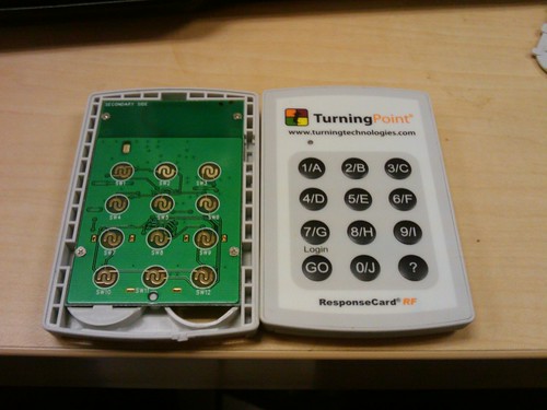
Turning Point Clicker

In this article, I describe in detail the methods by which I have reverse engineered the TurningPoint ResponseCard RF, casually known among students as a "Clicker". This 2.4GHz radio transceiver is used in undergraduate university classrooms for automated roll-call and in-class quizzing or voting. By dumping and analyzing its firmware, one can determine the radio protocol necessary to intercept and forge packets, as well as to build a custom base station. The radio hardware that I have used is a reprogrammed Next HOPE Badge running the GoodFET firmware.

A follow-up article will likely describe the writing of replacement firmware, but that can be easily enough discovered by an enterprising reader. My purpose instead is to provide the information necessary to build compatible products, as well as to teach the technique of reverse engineering these products to find such information when none is available.

Disassembly


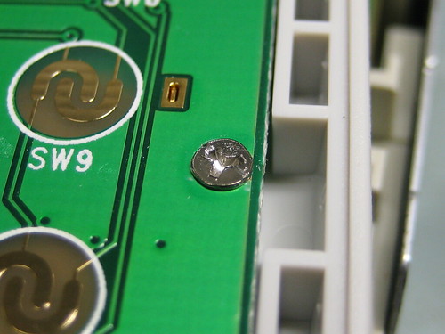
The Clicker's keypad is attached only with adhesive, and it can be pulled off after lifting an edge with a knife blade. Beneath the keypad, there are four screws holding the board in place, plus a fifth from the rear of the device. If you are lucky, these will be small Phillips screws, but the unlucky will find tri-wing "Nintendo" screws. I was lucky to have one of each type, but those with neither a Phillips-screwed Clicker nor a tri-wing screwdriver can buy one or try one of these tricks.
Devil Screws

In either case, it isn't strictly necessary to open your clicker, as test-points for dumping and replacing its firmware are accessible from the battery compartment. Further, the radio communications are accessible with no hardware access whatsoever.

Hardware


The Clicker is built upon a Nordic nRF24E1 chip, which combines an 8051 microcontroller with an nRF2401 radio transceiver. Although the two cores have been combined into a single package, the 8051 core speaks to the radio through a few bit-field registers and an internal SPI bus, which is shared with the external SPI bus.

As the nRF24E1 lacks internal non-volatile storage, a CAT25C32 (pdf) SPI EEPROM is used for program and configuration storage. Within the microcontroller, there is a masked ROM bootloader from 8000h to 81FFh that loads executable code from the EEPROM into executable RAM from 0000h to 0FFFh.

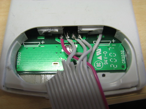
Hacked Clicker Board

Dumping Firmware


At the base of the circuit board's primary side, there are test points for the SPI EEPROM. As the default firmware only uses the SPI bus when buttons are pressed, this EEPROM may be dumped at any point after the device has booted. The test points are as follows, which should be matched to those of equivalent names in the GoodFET SPI Table. They were determined by use of a continuity tester.
T4MISO
T5SCK
T6MOSI
T3!CS
T1VCC
GNDGND


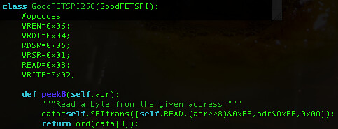
In order to dump the firmware, I quickly wrote a GoodFET client for the 25C32 using its datasheet. A read is performed by sending {0x02, AL, AH, 0} as a SPI transaction, with the result coming back as the fourth byte. Doing it this way with the GoodFET's SPI driver is slower than having C code within the GoodFET dump the whole ROM, but it's fast enough for a dump and takes very little code.
Quick and Dirty 25C32 Driver

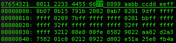
From this point, I dumped the firmware with 'goodfet.spi25c dump image.hex', converted the Intel Hex file to binary, and popped it open in Emacs/hexl. The result looks something like the following, whose format is described in the nRF24E1 datasheet. The opening passage is {u8 config, u8 entry offset, u8 blockcount}. Here {0x0B, 0x07, 0x0B} means that executable code begins at byte 0x07, and that the total image length is 0x0B*256==2,816 bytes. (Additional space within the SPI ROM is unused and left as 0xFF.)
Clicker ROM

To produce an image suitable for a disassembler, I cut the bytes before 0x07 to make an image beginning with {0x02, 0x0A, 0xB7, ...}. The extra bytes in this region are the serial number and default frequency, but we'll get back to that later.
Clicker Dev Kit

Firmware Analysis


As the firmware is only three kilobytes, it doesn't take terribly long to reverse engineer. First, the Special Function Registers (SFR) which are defined on pages 79 and 81 of the nRF24E1 datasheet are fed to the disassembler.

(I'm using IDA Pro here, but any 8051 disassembler with a decent text editor could suffice. All of the following function labels are from my imagination, while Special Function Registers (SFRs) come from the nRF24E1 datasheet.)

For example, "MOV 0xA0, #0x80" is rather opaque, but "MOV RADIO, #0x80" makes it clear that the immediate value 0x80 is being placed into the RADIO register. Page 89 of the datasheet will then explain that the high bit of the radio register is power control, so this instruction is powering up the radio for use. Similarly, "SETB RADIO.3" is setting the fourth bit of the RADIO register, which the datasheet describes as raising the CS signal.

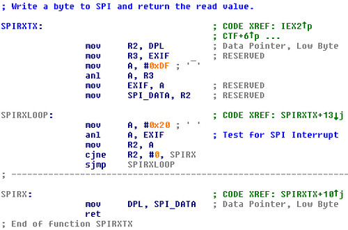
Once the SFR addresses are known, it becomes useful to search for them in order to identify the I/O routines. In the nRF24E1, the radio is accessed across a SPI bus, so a good first step is to identify the SPI routine. The function containing this code will always include a MOV involving the SPI_DATA register.
SPIRXTX for 8051

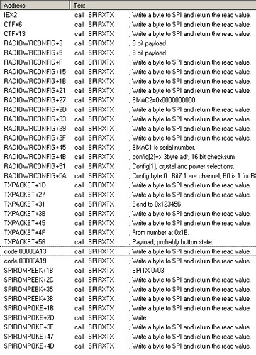
Having this, a list of cross-references quickly shows that while few functions call the SPIRXTX function, each calls it many times. This is because the author has chosen to repeatedly call that function with immediate values, rather than to dump an array of bytes with a for(){} loop.
Functions calling SPITXRX

While the disassembler can automatically identify the function entry points in the table above, it is not capable of giving them English names or descriptions. To understand how this is done, it is necessary to read the datasheets of the SPI devices.

The SPI EEPROM chip, a CAT25C32, is used by dropping the !CS line then writing an opcode byte followed by its parameters or results. Opcodes include WREN/WRDI for write protection, RDSR/WRSR for accessing a status register, and READ/WRITE for reading and writing bytes. A WRITE may only be performed when the external !WP pin is low and the software write protect has been disabled by opcode. A transaction begins when !CS drops low and ends when it drops high.

To identify the function which reads a byte from the 25C32, a few things can be safely assumed: (1) The function will begin by dropping some I/O pin (!CS). (2) The function will then broadcast the READ opcode, 0x03. (3) It will then broadcast a sixteen bit parameter; that is, DPL followed by DPH. (4) Finally, it will return the result of a fourth SPIRXTX call. In pseudocode, that would be something like
SPIROMPEEK(u16 ADR){
SPIRXTX(0x03);
SPIRXTX(ADRL);
SPIRXTX(ADRH);
return SPIRXTX();
}


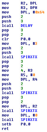
Sure enough, one of the few functions calling SPIRXTX does exactly this. The constant pushing and popping of the parameters is a quirk of the compiler, which might possibly allow it to be identified. From the code below, it is clear that P0.0 is the !CS line of the CAT25C32.
SPIROMPEEK

The SPIROMPOKE function looks similar, except that two transactions are performed. First the WREN (0x06) opcode is sent to enable writing, then WRITE (0x02) is used to perform the actual write.

The other SPI operations concern the nRF2401 radio core, which behaves differently from the EEPROM. Rather than transactions being an opcode followed by parameters, there is only a single SPI register that must be completely written during a transaction. A second register, selected by the CE line, contains the packets.

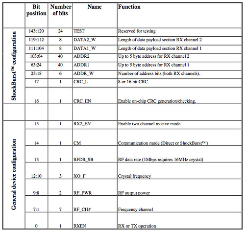
The configuration is set by one big register, sent MSBit first. If fewer than the needed bytes are sent, the value is right-aligned into the lower bytes of the register. That is, the last byte sent is always (CHAN<<1)|RXMODE and the second to last always describes the radio configuration.
nRF2401 Config Register

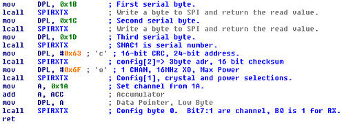
Searching around a bit yields the RADIOWRCONFIG function, the tail of which is below. It can be seen from the code that the 0x1A IRAM byte holds the channel number. That is, if 0x20 is stored at 0x1A, the radio will be configured to 2,432 MHz. The other configuration bytes reveal that the MAC addresses are 24 bits, the checksum is 16 bits, and the device broadcasts at maximum power sourced from a 16MHz crystal. (That the configured crystal is identical to the one on the board is very important. Some enterprising coders will lie to a chip about its crystal in order to access an unsupported radio frequency.)
Clicker RF Config

At this point, it still remains to sniff traffic is to find the target address to which packets are broadcast as well as the frequency. We'll start with the address, because that's a bit easier.

The TXPACKET function involves a lot of PUSH and POP instructions, but it otherwise looks very similar to the RADIOWRCONFIG function, in that a series of bytes are written in order with repeated function calls to SPIRXTX. In pseudocode, this function becomes the following. From the radio documentation and configuration, it is clear that the first three bytes will be the target MAC address. From the RADIOWRCONFIG() function, it is equally clear that the three bytes at 0x1B are the receiving MAC address of the unit. (The parameter of the function happens to be the button press, as can be determined by tracking the keyboard I/O routines or viewing a few packets.)
void TXPACKET(u8 button){
RADIOHOP(); //set channel

//Target MAC address
SPIRXTX(&0x1E);
SPIRXTX(&0x1F);
SPIRXTX(&0x20);

//Source MAC address
SPIRXTX(&0x1B);
SPIRXTX(&0x1C);
SPIRXTX(&0x1D);

//Data value
SPIRXTX(button);
}

The radio itself will append a 16-bit CRC; therefore, the full packet then becomes {u24 tmac, u24 smac, u8 button}.

To determine the value of the target MAC address, just grep the disassembly for "mov" and one of 0x1E, 0x1F, 0x20. The relevant instructions are as follows, setting the target MAC address to 0x123456. (In 8051 notation, the first instruction moves the immediate constant #0x12 into byte 0x1E of IRAM.)
mov 0x1E, #0x12
mov 0x1F, #0x34
mov 0x20, #0x56


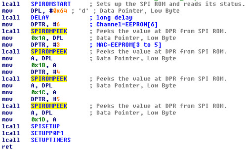
As this point, it would be possible to scan each channel for a few seconds, listening for packets sent to that address, but it's classier to find the value by static analysis. Acting on the hunch that the configuration is held in EEPROM and looking for references to the SPIROMPEEK() function, the READIDFREQ() function can be found. As can be seen in the fragment below, EEPROM[6] holds the channel number while the MAC address is at EEPROM[3,4,5].
Clicker Config

As the EEPROM begins with "0b 07 0b 15 79 1b 29", it's clear that the MAC address of the unit from which it came is 0x15791B and that it is broadcasting on 2400+0x29=2441MHz. This can be double-checked by the serial number "15791B" being printed on the label.

Implementation


Knowing the modulation scheme, target address, and packet contents, it becomes possible to sniff traffic from a Clicker. This is performed by use of the GoodFET firmware on a Next Hope badge, my prior tutorial for which describes the process of packet sniffing.

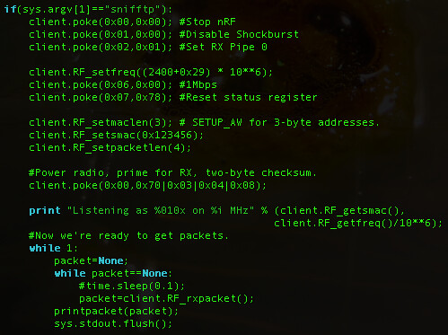
The NHBadge board contains an nRF24L01+ radio, which differs dramatically from the nRF2401 in terms of how it is configured. Still, the radios are sufficiently compatible. The following hack of the goodfet.nrf client allows packets to be sniffed from the air with proper checksumming.
Sniffing TurningPoint Traffic

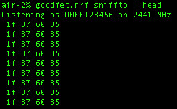
Sure enough, here are some packets of the 5 button being pressed on unit 1F8760. The keypress is the final byte in ASCII.
Clicker Sniffing

Response Codes


Now that it is clear how to receive and recognize button presses, it becomes necessary to reverse engineer the response codes which might be sent from the access point. Without hearing a reply of at least an ACK, the Clicker will continue to broadcast each message more than three hundred times. This takes more than ten seconds, during which all other key presses are ignored.

The broadcast loop within the MAIN() function would look a little like this in C.
for(count=0;count< MAXCOUNT && !reply;count++){
TXPACKET(button);
reply=RADIORX();
}
switch(reply){...}


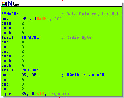
This region is easy enough to find, but there's another command mode. An easier target is the channel hopping routine, which constantly broadcasts 0x3F while incrementing the channel, sticking with the last one on which a reply of 0x18 was received. Channels 1 through 83 are attempted; that is, 2,401 MHz to 2,483MHz at 1MHz steps.
Clicker SYN/ACK

Checking this code within the MAIN() function reveals that its effect is to blink the green LED (P1.1) six times, exiting the broadcast loop. Other commands include 0x04 (LED Off), 0x06 (LED Green), 0x15 (LED Red), 0x11 (Blink Green), 0x14 (Blink Red), and 0x18 (Blink Green, Channel Lock). All undefined opcodes set the red LED.

Conclusions


By sniffing traffic within a classroom, it is possible to watch votes as they are being cast by students. Similarly, packets could be broadcast by a reprogrammed Clicker or NHBadge to make a student in virtual attendance, automatically voting with the majority so as to gain perfect attendance and a solid C quiz average. Where instant feedback is available, this might even allow for a solid A quiz average. Without taking advantage of the masked-ROM option of the nRF24E1, the code cannot be even slightly protected from extraction and reverse engineering.

Less adventurous users can jam the network by running 'goodfet.nrf carrier 2441000000' to hold a carrier wave on the channel. The only attempt at a frequency change is made when pressing the GO button, at which point the new channel can be discovered and similarly jammed.

Since performing this work, it has come to my attention that a USRP plugin for doing this to the competing 900MHz iClicker product is available as http://gr-clicker.sourceforge.net/. Additionally, the infrared Clicker units were broken with a little tool called Survey Says. I have ordered more sophisticated Clicker models from CPS and Turning Point, and proper descriptions of them will soon follow.