concerning the GirlTech IMME,
utilizing the GoodFET's Chipcon Debugger
to instrument Michael Ossmann's $16 Pocket Spectrum Analyzer.

Often a neighbor, such as myself, finds himself with a damned useful tool that's missing logging. Further, when this is a black-box application, it is undeniably inconvenient to patch in logging where no communications method exists. In this brief article, I will demonstrate how to instrument a Chipcon CC1110 application using Python and a GoodFET with zero bytes of modification to the original firmware image. My target's source code is available, but the technique applies just as well to black-box firmware.
Specifically, I want to dump the raw data from Michael Ossmann's $16 Pocket Spectrum Analyzer in order to demo it on stage at our Toorcon 12 talk, Real Men Carry Pink Pagers. I'll assume the reader to be familiar with Mike's article, as well as my article on wiring an IMME for debugging with a GoodFET. Readers wishing to play along can order a GoodFET31 for little or no money by following these instructions.
From the datasheet or Mike's Makefile it can be seen that the external RAM (XDATA, which is called external for historic reasons) section begins at 0xF000. The only structure at this location is xdata channel_info chan_table[NUM_CHANNELS], where NUM_CHANNELS is defined to be 132 and the channel_info struct is eight bytes, defined as
typedef struct {
 /* frequency setting */
 u8 freq2;
 u8 freq1;
 u8 freq0;

 /* frequency calibration */
 u8 fscal3;
 u8 fscal2;
 u8 fscal1;

 /* signal strength */
 u8 ss;
 u8 max;
} channel_info;
The first several entries in this struct might be as follows. The first of these lines defines the frequency to be 0x22af4b, the frequency calibration to be 0xef2c27, and the signal strength to be 0x41. The final byte defines the maximum strength, which is zero unless max-highlighting mode is turned on.
 22 af 4b ef 2c 27 41 00
 22 b1 43 ef 2c 27 3e 00
 22 b3 3b ef 2c 27 46 00
 22 b5 33 ef 2c 27 3c 00
 22 b7 2b ef 2c 27 44 00
 22 b9 23 ef 2c 28 3c 00
 22 bb 1b ef 2c 28 42 00
 22 bd 13 ef 2c 28 3f 00
 22 bf 0b ef 2c 28 3d 00
 22 c1 03 ef 2c 28 40 00
 22 c2 fb ef 2c 28 3d 00
 22 c4 f3 ef 2c 28 3e 00
 ...
This information can be extracted by halting and resuming the CPU, just as I did in my article on the PRNG Vulnerability of Z-Stack's ZigBee SEP ECC implementation. That is, GoodFETCC.CCpeekdatabyte() is used to grab these bytes from the CC1110's RAM. The following code dumped the fragment shown above.
#!/usr/bin/env python

import sys;

sys.path.append('/Users/travis/svn/goodfet/trunk/client/')

from GoodFETCC import GoodFETCC;
from intelhex import IntelHex16bit, IntelHex;
import time;

client=GoodFETCC();
client.serInit();

client.setup();
client.start();

bytescount=8*132;
bytestart=0xf000;

while 1:
    time.sleep(1);
    client.CChaltcpu();

    dump="";
    for foo in range(0,bytescount):
        dump=("%s %02x" % (dump,client.CCpeekdatabyte(bytestart+foo)));
        if foo%8==7: dump=dump+"\n";
    print dump;
    sys.stdout.flush();
    client.CCreleasecpu();
To get proper data, it is necessary to add a wake-up delay of a few seconds, so that the table is populated by the first sampling. Additionally, it is handy to convert the frequency to MHz from its native unit (Hz/396.728515625). Finally, successive pages should be separated by a time column in order to facilitate graphing. The result is this script, which can be found in the GoodFET project as "contrib/ccspecantap/specantap.py".
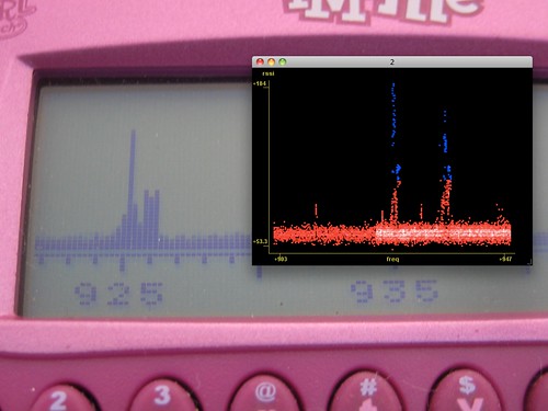
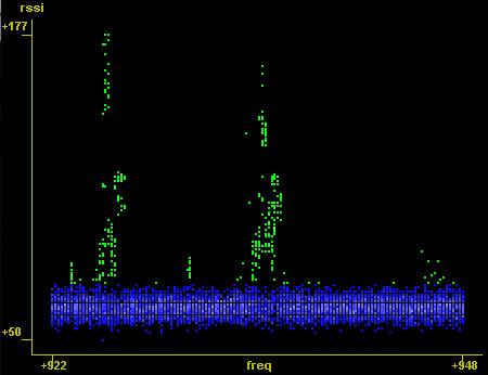
An example recording can be seen below, as a spectrum recording of a friend's Kenwood FreeTalk UBZ-AL14 FM Transceiver unit. This is compatible with other family FM radios, and I wanted to know which center frequencies were in use. In the first image, I've highlighted the noise floor as blue and the peaks as green. In the second image, the time domain is used to show broadcasts on several channels in sequence, all of which fall into one of the two center frequencies: 925MHz and 935MHz. The raw data is here, best viewed with NASA's excellent Viewpoints tool.


Future additions to this project will include integration into the GoodFET radio framework, as well as a 2.4GHz version built around the CC2430 and CC2530. The performance of the tap can be greatly improved by using block transactions rather than peeking individual bytes, and the view can be re-tuned by poking the configuration IDATA variables, positions of which are described in specan.rst as produced by the SDCC compiler.
It's also handy to know that a Chipcon radio will halt if the 0xA5 opcode is executed. In this manner, patching a single byte of a while() loop can allow the state at every iteration to be dumped.
This technique of scripted debugging through a programmer can be handy for more than instrumentation. Unit tests can be run on an assembly line without additional wiring, and--by single-stepping--execution traces of unknown firmware can be generated for assisting in reverse engineering. Those with enough patience can use this to fuzz test embedded systems for security vulnerabilities.
For help instrumenting your own Chipcon or MSP430 project, join us in #goodfet on irc.freenode.net or send me an email. The project has advanced to the point where interesting things can be done from Python alone, and I'd quite like to see what could be done with it.
