Friday, May 29, 2009

GoodFET11 Released

GoodFET12

The GoodFET11 boards have arrived for HardHack in Berlin, where they were assembled earlier today. It was quite neighborly to see that intelligent people with steady hands, but no prior practice, had little trouble assembling the GoodFET's surface mount components.

GoodFET firmware ought to be functional in the next week or two, with I2C and the Chipcon debugging protocol as the first targets. Please contact me if you are interested in writing a client application in Python or another unix scripting language.

--Travis Goodspeed
<travis at radiantmachines.com>

Friday, May 22, 2009

Black Hat '09, Defcon 17

Howdy y'all,

I'll be taking a trip to Vegas this summer for Black Hat and Defcon. Abstracts below are as submitted to the conferences, and there will be a tool released, of the extra-neighborly sort, at Black Hat. I also expect to do some hands-on stuff at Defcon's hardware hacking village.

For Defcon,
Locally Exploiting Wireless Sensors
Wireless sensors are often built with a microcontroller and a radio chip, connected only by a SPI bus. The radio, not the MCU, is responsible for symmetrical cryptography of each packet. When the key is loaded, it is sent as cleartext over the SPI bus, and an attacker with local access can steal the key using a few syringe probes and readily available hardware. This attack and other local attacks against wireless sensor networks will be presented in detail, including a live demo of an AES128 key being extracted from an operational network. Following the conclusion of the lecture, audience members will be brought onstage to perform the attack themselves on various pieces of example hardware.

For Black Hat,
A 16 bit Rootkit and Second Generation Zigbee Chips
This lecture in two parts presents first a self-replicating rootkit for wireless sensors, then continues with recent research into the security of second generation Zigbee radio chips such as the CC2430/2431 and the EM250.

--Travis Goodspeed
<travis at radiantmachines.com>

Tuesday, May 19, 2009

MSP430 Challenge of May 2009

Howdy neighbors,

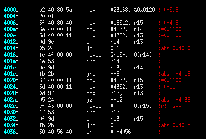
The following image is a piece of disassembled code that was compiled for the MSP430F1611. The code is found in many programs, but in this one it is accidentally vestigial as a result of a compiler bug. Please comment as to (1) which compiler generated the code, (2) what the code was intended to do, and (3) why the code is vestigial in the example, but might not be in another program. Translations to C or psuedocode and commented write-ups are also nice. The MSP430F1xx Family Guide might be handy if you're unfamiliar with the architecture.

I'll send a GoodFET board to the most insightful commentator, but as I send those boards out to anyone who asks, you're really only commenting for the neighborliness of it all. If I get enough replies, I'll post one of these each month.

Also, I saw a lot of good work on last month's Masked ROM Challenge while I was a Cleveland, but next to nothing has been sent my way. If you made significant progress, such as semi-automated extraction of the bits, please email me.

--Travis Goodspeed
<travis at radiantmachines.com>

Disassembly Challenge

HardHack and PH Neutral, Berlin

Last Night in Knoxville

On April Fool's day, I jumped into my car and left Knoxville to wander the world in search of neighborliness. Now I find myself in Berlin, finishing up some projects and living on döner.

At the end of this month, I'll be giving a workshop at HardHack on Friday 29 May on the GoodFET project. No slideshow, no projector, just a good old fashioned, informal sermon on the design as we build a few USB JTAG adapters then program them. Sign-ups for the workshop are here.

The GoodFET is self-programmable by USB, so upgrading firmware requires no additional hardware. As this is surface-mount, you'll need to have a steady hand and good eyesight. I've ordered parts and boards for the GoodFET11, with the GoodFET10 as a backup if the boards don't arrive in time.

On Saturday 30 May at 15h00, I'll be presenting at PH Neutral. Everything about the talk is a surprise, except that it involves embedded systems.

--Travis Goodspeed
<travis at radiantmachines.com>

Friday, May 15, 2009

Microchip Zena Reversed

Howdy y'all,

Neighbor Joshua Wright has reverse engineered the Microchip Zena Zigbee sniffer's USB protocol, allowing packets to be dumped and channels to be hopped from Linux. Kismet support is the next step.

The EZ430RF2500 uses similar tricks in Windows with its HID driver, making Linux support quite difficult. If you have a Windows machine and are interested in doing the same to the RF2500 kit, please send an email my way, with a carbon copy to Josh.

--Travis
<travis at radiantmachines.com>

Wednesday, May 13, 2009

FET Firmware from MSP430.DLL

by Travis Goodspeed <travis at radiantmachines.com>

The firmware of the MSP430 FET is distributed for purposes of upgrades within MSP430.dll. In this brief article, I'll describe its location and a method for extraction.

Firmware as Regions


All of these examples will use MSP430.dll with the following checksum. My previous FET articles have used a firmware image from the last revision of libMSP430.so, so addresses and code fragments will differ slightly.
f0685a0eca0545dfc542530afff8159f
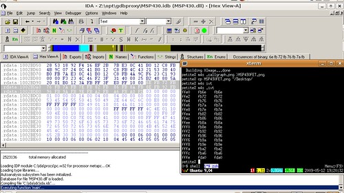
MSP430 FET IVT in MSP430.dll

A bit of quick searching reveals that the firmware of the MSP430 FET is contained within MSP430.dll as little-endian words at these addresses.
Bootloader code at offset of 0x1BFE8, region [0xF800,0xFFE0).
Application code at offset of 0x1EB38, region [0x2500,0xF7E0).
IVT at offset of 0x1BDBC, region [0xFFE0,0xFFFF].

That is, to recover the bootloader, copy 32 bytes (0x10000-0xFFE0=0x20) from the DLL at (0x1BDBC+0xFFE0=0x2BD9C) offset to the target MSP430 image at 0xFFE0.

Below are memory maps of my first attempt at extraction and an old EZ430 FET. It's clear that a lot of junk has been included by accident, which is why tabular entries, rather than regions should be used.

MSP430FETEZ430U Memory Map

In addition to the large segments, there are also a few scattered bytes that form the lower IVT. (See Repurposing the TI EZ430U, Part 3 for an explanation of why there are two Interrupt Vector Tables.) Because the lower IVT is sparse, only those words which are not 0xFFFF are included. For example, the lower RESET vector--which, incidentally, is never read by the bootloader, in which the lower RESET is hard-coded--resides at 0xF7FE and points to 0x2502.

Searching MSP430.DLL for the interrupt vector, "02 25", yields a few results, one of which is "fe f7 d9 02 02 25". That's quite clearly an entry in a table of some sort. Searching around it yields a few more entries.


Firmware as a Table


By this point is should be clear that while it might be possible to extract the different fragments of the firmware manually, it would by much nicer to dump the whole damned thing as a table. This can be done.

Each entry is of the form {adr, len, data} where adr is the 16-bit address of the fragment within the firmware image, len is the length of the data in 16-bit words, and data is a collection of 16-bit words as little-endian. Following one entry is another, ending with an invalid address. (Anything less than 0x200 is I/O, anything less than 0x2500 is not flash.) Adding 4+(len<<1) to an entry's pointer gives the next entry.

Using this technique and finding an initial entry point of 0x21036, I generated a dump that produces the following image (left) as compared to the previous attempt (right).
MSP430.dll FET FirmwareMSP430FET

The new attempt contains everything important, including a few bytes which were missed in the first attempt. It also lacks all of the vestigial bytes that got roped in by the previous method. Further, as each binary is defined by a single entry point, it shouldn't be terribly difficult to search for the entry point in order to generically dump any version of the library.

This cleanliness is confirmed by the callgraph below, which properly shows no function calls between the bootloader (right) and the application (left). (Branches are not graphed.)

MSP430.dll FET Firmware

The Code


The MSP430 Flash Emulation Tool's firmware is available for free download in MSP430.DLL, and anyone wishing to experiment with it need only download the library and extract the code.

A hastily written extraction utility can be found by subversion. A screenshot follows.
svn co https://goodfet.svn.sourceforge.net/svnroot/goodfet/contrib/fetextract

FET Firmware Extraction

Saturday, May 9, 2009

UART Sniffing Notes

by Travis Goodspeed <travis at radiantmachines.com>
concerning a collaboration with Reilly Grant.

The following are some brief notes on asynchronous serial traffic, how to decipher it, and how to identify a baud rate when a scope is unavailable.

RS232, TTL UART Waveforms


RS232 Serial
TTL Serial

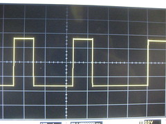
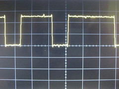
Of the two waveforms above, the first is RS232 and the second is TTL-level serial. They are on opposite sides of a MAX232 level-converter, and the images have been scaled to show the same point in the transmission, which is inverted and amplified by the MAX232. Here, the TTL line is +5V for a 1 and 0V for a 0. The RS232 line is -10V for a 0 and +10V for a 1.

In decoding serial traffic, it is important to recognize that the least significant bit is transmitted first, and that it is preceded by a start bit of 0. Following the most significant bit will be an optional parity bit and stop bit of 1. Thus, 0xEE would be
111111110011101111111111
where the bold portion is the data byte and the surrounding ones are the idle state. For practice, draw arbitrary bytes on paper, both as RS232 and as TTL-level. Further, note that the exact end of the byte is not immediately clear, and can only be found by matching timing from the starting 0 bit.

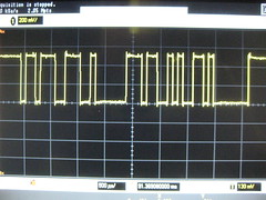
Here is a photograph of a few bytes.
Smart Card ATR

Double Timing


Sniffing at the wrong rate.
When decoding serial traffic, it is crucially important to do so at the proper rate. It is for this reason that the standard baud rates have been decided upon. The traffic above was received at roughly, but not quite exactly, twice its baud rate. Note--by clicking the image for a better view--how common bytes of 0xFF and 0x00 are, as well as how rare a byte containing just a single 1 or 0 in isolation is.

Close Timing


Once sniffing traffic on the proper order of magnitude, it is often the case that a smart card reader will not be using exactly the same timing. As timing is synchronized not to a clock, but to a start bit, the less significant bits will be correct with errors being found in the more significant bits. For example, "0x3B 0x02" might be mistakenly read as "0x9B 0x82" if the transmission is being sniffed at a slower rate than the actual. This is because the stop bits are being misinterpreted as most-significant bits. (10,400 baud being sniffed at 9600 baud, in this case.)

To determine the next guess from an incorrect read without a scope, draw the misinterpreted byte and the correct byte of graph paper, comparing them. Shown below are 0x3B and 0x9B, click on the image for annotations.
Bytes

Unfortunately, Unix was not designed with odd baud rates in mind, and the Linux solution isn't terribly elegant either. In short, you must configure the port to run at 38,400 baud and override that baud rate with a manually chosen clock divider. For details, see the setserial documentation, looking at the spd_cust option. Further complicated matters, spd_cust doesn't seem to work with the FTDI usb/serial chip. If you can get the chip to work at an odd rate, please post a comment with details.

Automation


Automatically identifying the baud rate isn't terribly hard for a microcontroller, which can watch traffic to measure the bit width and adjust its reception appropriately. At some point, I'll write firmware for the MSP430 to do just that.