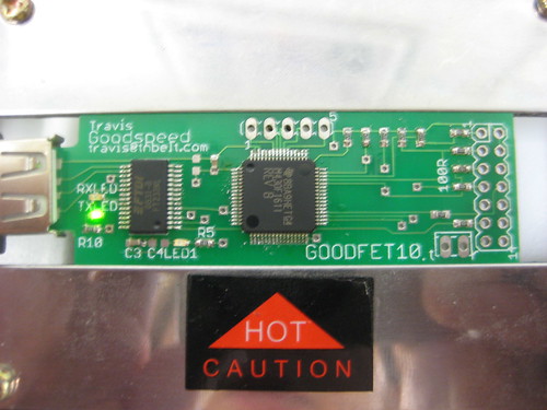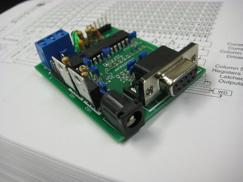
To celebrate 4/30 day, I am happy to announce my own variant of the MSP430 FET debugger. My variant is compatible with a patched version of the original firmware, but my goal is to eventually have open firmware as well.
For an overview of the internal functioning of the original FET, see my three part series on Repurposing the EZ430, or torrent my 25C3 lecture on the same topic.
For the purposes of this discussion, a FET is any Flash Emulation Tool containing an MSP430F1612, including the FET UIF and EZ430 debuggers. The parallel-port FET operates differently and is outside the bounds of this discussion.
To follow along with this discussion, be sure to print the FET schematics from the relevant TI application notes. The FET UIF's schematic can be found on page 64 of SLAU138K. Version 1.0 of the EZ430U can found on page 12 of SLAU176B, while Version 2.0 can be found on page 13 of SLAU227B. As I've likely made a few mistakes in the write-up, please kindly inform me of them.
FT232 for TUSB3410
All present FETs use the TUSB3410 usb to serial converter. Support for this chip is a pain in Linux, with kernel module requirements varying often. It's so bad that I keep a script in my private svn repository for fixing support as quickly as possible, and despite the recent appearance of open FET clients, using them on an obscure operating system is impossible without kernel support.
Internally, the '3410 is an 8051 microcontroller with a USB 2.0 Full Speed (12Mb/s) peripheral and a single UART. The traditional FET and most other devices use this chip with its default usb/serial firmware, but the second-generation EZ430 firmware uses various tricks to make a second, bit-banged, asynchronous serial port to the debugging target. On Windows, this leads to reliability issues, and on Linux, this leads to utter incompatibility. The '3410 also requires several external components, complicated the design and making hand soldering less feasible.
The FT232R from FTDI is a perfect replacement. It is available in an SSOP28 package for easy soldering, every operating system on Earth supports it, and its only external components are decoupling capacitors.
Bootstrap Loader
The MSP430 Bootstrap Loader (BSL) and I have had some good times together. While I still consider it to be a security risk for locked devices, it's damned handy for an unlocked board such as the FET. Likely for historical reasons, the BSL runs on P1.1 and P2.2, rather than the hardware UART pins. It also requires a special reset sequence, in which the RTS and DTS serial lines are connected to the RST and TCK pins.
Early revisions of the FET did not connect the BSL I/O pins, making the software bootloader that I describe in my articles on the EZ430 necessary. (The FET and first-generation EZ430 share a flash bootloader, while the second-generation EZ430 has a different, larger bootloader.) While later hardware revisions of the UIF connect the BSL pins, I've not seen the masked-ROM BSL used in practice. My design supports the BSL, preventing bricking and allowing for TI's firmware and open firmware to be exchanged at a whim.
To program the board by BSL, use tos-bsl with the --invert-reset and --invert-test switches.
MSP430F1612/1611
The MSP430F1612 was chosen for compatibility with the original FET. It has 55K of flash and 5K of RAM. Alternately, the MSP430F1611 with an identical footprint might be used for applications which require additional RAM but are willing to use less flash, at the expense of compatibility with the original chip. (MSP430 firmware grows upward from the bottom of flash memory, making it easy to port code from a device with less flash to a device with more, but difficult to port in the opposite direction.)
All custom firmware should be compiled to run in the intersection of memory of the two chips. In that way, most applications will run on either chip, with only those that need more stack depth requiring the 1611 and only those requiring more flash memory requiring the 1612.
Crystals
The MSP430 supports both high-speed and low-speed crystals, with the low-speed crystal's frequency being multiplied. Stable timing is not necessary for synchronous protocols such as JTAG or Spy-Bi-Wire, but only for asynchronous serial communication. While the EZ430 and FET firmwares both demand high-frequency crystals for absurdly high serial baud rates, I expect to reduce the data rate and source an external low-frequency crystal to reduce the parts count.
It is also possible to use bit-banged serial, or to call bit-banging serial routines from the bootloader (BSL) ROM. The BSL's code is particularly elegant because it resyncs the timing with the 0x80 SYN byte. This byte in 8/E/1 (8 bits, Event parity, 1 stop bit) appears as 8 marks surrounded by spaces, so rather than being read it is measured. The measured width is right shifted three times to get a bit's width, then once more for a half-bit. This measurement is used to bit-bang one transaction, then a new measurement is made for the next transaction. In this manner, even without a crystal, the BSL is able to perform fast, reliable serial communication in spite of clock drift. By calling this code--which is already resident in each chip--crystal-free operation is possible.
A high-frequency crystal is required to run unpatched variants of TI's firmware, but I've decided against including one in the design at this stage. Perhaps this will change in the future.
I/O Pins
The first four pins of P5 are used as JTAG and SBW I/O. Starting with P5.0 and continuing to P5.3, they are TMS, TDI, TDO, and TCK. I've chosen to omit the FET UIF's optical isolation in favor of the EZ430's simpler protection, which consists of 47K pull up resistors and 100R current-limiting resistors. Unlike the EZ430, which only support spy-bi-wire, my design has a full 14-pin JTAG connector.
Firmware, Old

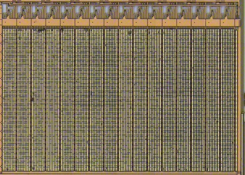
The above image is the firmware of an EZ430U FET, generated by msp430static. 0x0000 is the bottom left corner, 0xFF00 the top left, and 0xFFFF the top right. Blue represents the target of an immediate pointer, black is empty flash memory, red is potentially executable code, and grey is information which is certainly not executable.
The image is composed of two parts. The upper red region is a bootloader which is used to reflash the chip, while the lower region does the actual work. As compilers ship with firmware upgrades, it is not necessary to distribute any copyrighted code. A replacement bootloader could accept a firmware upgrade, then patch it, while retaining software compatibility. More information on the bootloader can be found in Part 3 of my series on repurposing the TI EZ430U.
Firmware, New
Ideally, replacement firmware will be written for various applications, beyond MSP430 debugging. The same hardware could program competing microcontrollers, serial eeproms, FPGAs, and all sort of other things in the same way that the Hackaday Bus Pirate does.
So far as replacement firmware for debugging MSP430 chips goes, documentation is slim. Enough of the JTAG protocol has been documented to implement programming, but the setting of hardware breakpoints and other advanced features are not described by any public documentation. Custom firmware is not yet functional, but that ought to change in the near future.
Second Serial
The red board variants of the EZ430, those shipping with the RF kits, use drastically different firmware to facilitate a second serial port that connects to the target board. This breaks Linux compatibility, requiring firmware of both the MSP430 and the CAT24 EEPROM of the board to be downgraded.
To support low voltage serial communications, I brought out the second UART of the board's MSP430 to test points. This might also be used for timing attacks or similar things. Series and pull-up resistors would be nice on these lines, but they were omitted in the first design.
Availability
I've ordered a panel of the first revision, GOODFET10, and I'll send a board to anyone who is willing to assemble the device and help construct its firmware. Schematics, gerbers, and construction details have been posted to http://goodfet.sourceforge.net/, and "hello world" firmware has already been committed to the subversion repository.


