Tuesday, December 30, 2008

Sniffing the MSP430 FET Protocol

by Travis Goodspeed <travis at radiantmachines.com>
regarding his independent recreation of anonymous, unpublished by other neighborly fellows. update: see here for the original implementation.

As the MSP430's gdbproxy relies upon closed-source libraries, which are not available for platforms other that Windows and i386 Linux, it would be valuable to generate an open-source alternative. Further, these closed libraries do not allow the debugging of all MSP430's. As reverse engineering the protocol by code review would be prohibitively complicated, grabbing serial traffic is an effective alternative. The following method allows for the dumping of serial frames for later analysis.

It is also a worthy goal to reverse engineer the proprietary aspects of TI's JTAG standard, but that is not the subject of this article. Here I will only investigate the protocol between a workstation and the MSP430 JTAG tool.

The simplest means of doing so is by using LD_PRELOAD to proxy--and print--calls to the write() and read() methods. To do so, I authored serspy.

Serspy works by proxying each call to the read() and write() system calls. For example, to trap the write() command,

//trap the write command
static ssize_t (*_write)(int fd, const void *buf, size_t count)=0;
int write(int fd, const void *buf, size_t count){
int num;

//This grabs a pointer to the original function.
if(!_write)
_write=(ssize_t (*) (int fd, const void *buf, size_t count)) dlsym(RTLD_NEXT,"write");

//Now really write.
num=_write(fd,buf,count);

//And log it.
logdataw(fd,buf,count);
return num;
}

The code above is a replacement for the write() function which uses dlsym() to request a pointer to the original write() function, to which it forwards the call before logging it. As msp430-gdbproxy doesn't link against libdl and it is a 32-bit application, LD_PRELOAD must be set to ``./serspy.so:/usr/lib32/libdl.so''. Further, serspy.so itself must be compiled with the -m32 switch on 64-bit workstations.

Consider an example transaction, such as
W  7e 01 01 16 07 7e
R 0c 00
R 01 02 00 00 01 00 50 9e 98 00 67 4b


Writes (W) from the workstation begin and end with 0x7e, which never appears within the request. An encoding method of some sort is used to remove them. Reads (R) from the FET device begin with a 16-bit, little endian length. Following this length are the bytes themselves.

Consider also the following Writes, all of which are fetches for memory.
x/h 0x0200
7e 0d 02 02 00 00 02 00 00 02 00 00 00 b0 17 7e
x/h 0xfc00
7e 0d 02 02 00 00 fc 00 00 02 00 00 00 c0 06 7e
x/h 0xfc02
7e 0d 02 02 00 02 fc 00 00 02 00 00 00 af 0d 7e

All addresses are found intact as little endian: "00 02" for 0x200, "00 fc" for 0xfc00, and "02 fc" for 0xfc02. That won't be true for bytes which contain illicit characters, as I'll demonstrate later. Also note that the final two bytes of each message vary drastically; these are most likely a checksum of some sort.

Regarding the checksum, there are two common possibilities. The first is a CRC16 checksum, while the latter is the XOR of all transmitted bytes. The MSP430's serial bootstrap loader uses the latter method, but it is easy to rule out here. As the examples above for fetching 0xfc00 and 0xfc02 differ by only one bit apart from the checksum, yet the checksums show no resemblance, this checksumming function must be more complicated. A solution to the checksumming problem will be presented in a later article.

Illicit characters are dealt with by escaping. Consider the following queries,
x/h 0xeeee
7e 0d 02 02 00 ee ee 00 00 02 00 00 00 5c ac 7e
x/h 0xee7e
7e 0d 02 02 00 7d 5e ee 00 00 02 00 00 00 c6 3c 7e
x/h 0xee7d
7e 0d 02 02 00 7d 5d ee 00 00 02 00 00 00 16 b6 7e
x/h 0xee7f
7e 0d 02 02 00 7f ee 00 00 02 00 00 00 79 bd 7e
x/h 0xee7c
7e 0d 02 02 00 7c ee 00 00 02 00 00 00 a9 37 7e


From this it can be seen that 0x7d is the escape character, and that 0x7d and 0x7e are the characters to be escaped. Each is escaped by following 0x7d with either 0x5e or 0x5d, taking the lesser nybble.

Performing a few more queries exposes the length field of the memory read, as queries for 2, 1, and 4 bytes yield
x/h 0xeeee
7e 0d 02 02 00 ee ee 00 00 02 00 00 00 5c ac 7e
x/b 0xeeee
7e 0d 02 02 00 ee ee 00 00 01 00 00 00 91 89 7e
x/w 0xeeee
7e 0d 02 02 00 ee ee 00 00 04 00 00 00 c6 e7 7e


The first byte after the frame-start is 0xd, which is also the first byte of the response. Taking this further, a command/response code can be discovered, which is the first byte of both the encapsulated request and the response. In the follwoing case, an examine query has the code 0x0d while the set query has a code of 0x0e.
set *0xffd0=0xdead
W 7e 0e 04 01 00 d0 ff 00 00 02 00 00 00 ad de 49 6e 7e
R 06 00
R 0e 00 00 00 9c 52
x/h 0xffd0
W 7e 0d 02 02 00 e0 ff 00 00 02 00 00 00 4d b6 7e
R 0c 00
R 0d 03 00 00 02 00 00 00 ff ff 03 b8


This series will be continued once the checksumming routine has been reimplemented, at which point a custom client may be written.

See this post for details on my implementation.
Tuesday, November 25, 2008

25C3 Workshop

I'll be giving a workshop on Repurposing the TI EZ430U at the 25th Chaos Communications Congress, Berlin. It will be on Day 3 (2008-12-29 Mon) from 16h00 to 18h00.

There's no charge for the workshop beyond conference admission, but please attend the lecture and bring an EZ430 with you if at all possible.

Cheers,
--Travis
<travis at radiantmachines.com>

Wednesday, November 19, 2008

Radiant Machines

I've started a site, http://radiantmachines.com/ to showcase my collaborations with Josh Gourneau. The first is a belt buckle.

--Travis
<travis at radiantmachines.com>

Friday, November 14, 2008

Speaking at 25C3

BSLCracker 3.0

At the 25th Chaos Communications Congress in Berlin this December, I'll be presenting some new research in the security of the MSP430's serial bootstrap loader (BSL) as well as a nice little lecture/workshop combo on reverse-engineering the TI EZ430 development tool.

I intend to travel through France and England, returning in late January for S4, Miami. Please email me if you'd like to meet.

Cracking the MSP430 BSL
Day 1 (2008-12-27), 20h30 (8:30 pm) in Saal 3.

The Texas Instruments MSP430 low-power microcontroller is used in many medical, industrial, and consumer devices. When its JTAG fuse is blown, the device's firmware is kept private only a serial bootstrap loader (BSL), certain revisions of which are vulnerable to a side-channel timing analysis attack. This talk continues that from Black Hat USA by describing the speaker's adventures in creating a hardware device for exploiting this vulnerability.

While the previous part focused on the discovery of the timing vulnerability and its origin, this lecture will focus on the exploitation. Topics include a brief review of the vulnerability itself, PCB design and fabrication, the malicious stretching of timing in a bit-banged serial port, observation of timing differences on the order of a microsecond, and the hell of debugging such a device.


Repurposing the TI EZ430U
Lecture: Day 3 (2008-12-29), 12h45 (pm) in Saal 3
Workshop: Not yet scheduled.

USB devices are sometimes composed of little more than a microcontroller and a USB device controller. This lecture describes how to reprogram one such device, greatly expanding its potential.

At only twenty dollars, the Texas Instruments EZ430U is a bargain of an in-circuit debugger for the MSP430 microcontroller. The board itself is composed of little more than an MSP430 and a USB to Serial controller. The board's JTAG fuse is unblown, and full schematics are included in public documentation. This lecture will discuss the use of the EZ430U, not as a debugging tool, but as a development platform in and of itself. Topics will include the writing of replacement firmware, analysis of the default firmware, reprogramming the USB to Serial controller, and potential target applications.


--
Travis Goodspeed
<travis at radiantmachines.com>

Tuesday, November 4, 2008

MicaZ Code Injection

by Travis Goodspeed <travis at utk.edu>

Aurélien Francillon and Claude Castelluccia of France's INRIA recently demonstrated at CCS2008 a code-injection attack that reflashes Mica wireless sensors. This is more difficult than my TelosB attack because the MicaZ uses a Harvard-architecture CPU, one that is incapable of directly executing RAM. The authors use meta-gadgets, collections of executable code found already within the device, to copy the payload into executable flash memory. It's about damned time that someone authored a practical implementation for those things, and the paper is well worth reading.

If you quickly glance over the paper, you might miss the best part, which is not that the authors used meta-gadgets but exactly how they found the meta-gadgets. See the seventh page of their paper, the section entitled `Automating the meta-gadget implementation', for details of a modified CPU simulator that constructs meta-gadgets automatically from a given firmware image.

Sunday, November 2, 2008

Speaking at S4 in Miami


On Thursday, January 22nd, I'll be presenting at Digital Bond’s SCADA Security Scientific Symposium (S4) a paper authored with Brad Singletary and Darren Highfill of Enernex on the topic of Low-Level Design Vulnerabilities in Wireless Control Systems Hardware. As 802.15.4 sensors and similar hardware are subject to theft by an attacker, we demonstrate several practical attacks that we've been cooking up for the past year. We include plenty of schematic diagrams, logic analyzer recordings, oscilloscope photographs, and code fragments to keep things interesting. Attendance is strictly limited to fifty-five, and registration is expected to sell-out this year.

Please email me if you'd like to meet up while I'm in town. As always, I'll bring some of my equipment for a show and tell.

Cheers,
--Travis Goodspeed
<travis at utk.edu>

Tuesday, October 28, 2008

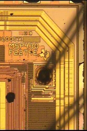
The MSP430F2254 is a 2274.

MSP430F2254, a 2274 in Disguise

A few weeks back, I ran out of MSP430F2274 chips and used the pin-compatible 2254 for a few of my BSLCracker boards. After connecting a FET to program the first of them, I found that GDB mistook it for a 2274. The chip ID of a 2254, beginning at 0xFF0 and continuing as big-endian quartets, is "F2274". The photograph above, taken by Brooke Hill, confirms that the die of the MSP430F2254 is that of a 2274.

What method is used by TI to downgrade a '74 to a '54, and is it reversible? Please email me if you can shed any light on the matter.

Cheers,
--Travis Goodspeed
<travis at utk.edu>

Monday, September 29, 2008

Speaking at PumpCon 2008 in Philly

Howdy Y'all,

I'll be driving to Philadelphia on Friday, October 24th to speak at this year's PumpCon. This lecture continues that of Black Hat USA, focusing on the exploitation--rather than the origin--of timing vulnerabilities that I've found in certain revisions of the MSP430's serial bootstrap loader.

--Travis Goodspeed
<travis at utk.edu>

Monday, September 15, 2008

Repurposing the TI EZ430U, Part 3

by Travis Goodspeed <travis at utk.edu>
of Southern Appalachia

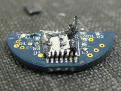
Shattered EZ430T2013

The first installment of this series described a method of accessing the EZ430's MSP430 firmware by way of JTAG, while the second installment took a detour to discuss the TUSB3410 usb controller of the board. This third installment is concerned with the analysis of the green EZ430U firmware; that is to say, it is concerned with the firmware of the six-pin EZ430f2013 kit, which might differ from the four-pin EZ430f2013 kit and drastically differs from the red EZ430rf2500 kit.

Section 1, wherein we make general, even visual observations regarding the organization of firmware, as well as the locations of important objects.

Observe the following memory map, which was generated by the .memmap.gd.xview macro of msp430static.

In an m4s memory map, the X axis represent the less-significant byte while the Y axis represents the more significant byte. 0xFF00 would be the top left, and 0xFFFF would be the top right. As the interrupt vector table (IVT) of the MSP430f1612 ranges from 0xFFE0 to 0xFFFF, it appears as a green band in the upper right of the image. Entries within it all point to the upper red band, with addresses varying from 0xfb78 to 0xfdb0, in regular increments of 4. The only exception to this rule is the RESET vector at 0xfffe, which points to 0xfdaa.

Why such an arrangement? Each of these regularly-spaced interrupt handlers is a branch to a lower interrupt handler. The blue line that you see at the top of the black expanse is a second IVT, entries of which are called from above. 0xffe0, the DMA vector, point to a branch to &0xf7e0, which is to say that address which is contained within 0xf7e0. Similarly, 0xffe2 points to a branch to 0xf7e2. In fact, every interrupt except for RESET points to nothing but a branch to its equivalent in the table that begins 0xf7e0.

It should be clear, then, that not one but two programs reside in this image. The first-stage firmware, which rests at the top of memory, performs its own initialization when the chip is reset, but differs all interrupt handling to the lower firmware, which grows from the beginning of flash to 0xf7e0. It shouldn't be hard to instruct a compiler to build a second-stage firmware compatible with the first-stage, but it would be imprudent to spring into such a task without at least a casual analysis of the first stage.

Section 2, wherein we examine the first-stage firmware in depth.

The first-stage firmware is a bootloader which resides from 0xf800 to 0xffff in flash memory of an MSP430F1612. A quick search with MSP430static--which I'll refer to as 'm4s' for the sake of brevity--reveals that 30 functions have been found in this area. Fifteen of these, those in the range [0xfb78,0xfbb0], are merely branches to interrupt handlers in lower memory. The interrupt handler is a function which I'll call init() that resides at 0xfdaa, calling a config() function at 0xf828 to set registers to their proper values. The only call made by config() is to delay() at 0xf812 that uses nested loops to implement a timing delay.

I/O is performed by putbyte() and getbyte() functions at 0xfbc6 and 0xfbd2 respectively. These use USART0 in UART mode. This port is configured, as are many other peripherals, in the previously mentioned config() function.

As the purpose of this series of articles is to describe the process for writing a complete replacement firmware, I should mention that such information is to be found within this stage. Port 3 is especially important, as it is tied into both UARTS and I2C. As you'll recall from the early articles of this series, the TUSB3410 refuses to load with ports in the default configuration. By matching the configuration of the original firmware, we ought to be able to get something going.

To that end, Port 3 is configured as follows within the config() function.

f88e: bis.b #48, &P3SEL
f894: bis.b #16, &P3OUT
f89a: bis.b #16, &P3DIR


Clocks and such must also be reconfigured, but I come bearing good news! There's an easier way, in that by relocating the IVT or reconfiguring your compiler, you can generate a custom second stage firmware without rewriting the first stage.

Section 3, wherein we examine the second-stage firmware in brief.

By comparison to the simple, neighborly firmware of the preceding section, the second stage firmware is gigantic and multi-tasking, with a rats-nest of function calls to a few key functions. Although it serves little immediate value, I'll cover second stage as an example of a few analysis techniques.

Which function calls are most popular, and what do they do? The .calls.top10 macro results in the following:
163     4c3e    4c3e
151 4f54 4f54
142 4b6a 4b6a
29 4eca 4eca
28 6100 6100
27 2ba2 2ba2
24 8d0e 8d0e
24 a784 a784
20 5f4c 5f4c
17 756e 756e

Note the sharp dropoff after the third. In a multi-tasking application, such as a TinyOS wireless sensor node, it would be logical to assume these to be mutex locks. In a JTAG adapter, however, it is much more likely that these serve an I/O purpose. Sure enough, all three are I/O related with 0x4f54 performing I/O through function calls and the other two doing it directly.

As I am not concerned with reverse-engineering the TI's proprietary debugging protocol, but rather only with making software capable of running on the EZ430 programmer, I'll delve no further into the second-stage firmware. Remember only the following: (1) That the IVT of the second-stage code resides at 0xf7e0, (2) that all else remains unchanged.

The question then becomes one of relocating the IVT, which may be accomplished either by altering linker scripts or by rewriting the firmware image before flashing it to the device. We shall begin with the prior method.

Section 4, wherein we rewrite the linker scripts of two popular compilers so as to generate our own second-stage code for this fine platform.

Moving the IVT is accomplished in GCC by forking msp430x1612.x to ez430u.x, then changing line 8 to the following:
vectors (rw) : ORIGIN = 0xf7e0, LENGTH = 0x20
Call GCC with the -T switch followed by your forked linker script, and the output will direct to the proper address. Use msp430-objdump to verify the address in your output. For further details, consult my article on Retargetting the MSPGCC Linker. In the case of the IAR compiler, the IVT range is defined near the end of lnk430F1612.xcl.

Please note that, for no reason that I can fathom, the RESET vector of the second-stage IVT has been hard-coded to be 0x2502 in some places. You must set the .text section to begin at 0x2502, or the reset will land in the middle of a two-word instruction.

Section 5, wherein your author makes a shameless plug his upcoming appearance at the tenth annual Toorcon San Diego but provides little else of substance.

A fourth installment of this series will wrap up the replacement MSP430 code, concluding with a complete and commented `hello world' example for GCC.

Monday, September 8, 2008

Errata from Black Hat USA 2008

MSP430F1101A control flow diagram

There exist two errata, one trivial and one substantial, in my Black Hat presentation.

First, Vcc of the 2013 chip in the schematic diagram should be connected to Vcc of the JTAG/SBW connector, not Vext as is shown in the schematic. I had to score and solder those in my prototype, but I forgot to update the slides. (The new unit uses the MSP430F2274, regardless.)

Second, and much more substantially, memory is erased by default on reception of an incorrect password unless BSLKEY is set to 0x0000 on BSL version 2.0+. See page 11 of SLAA089D for details. You will find the code responsible at 0xD66 within the password comparison routine of the MSP430FG4618 Rev. G BSL, version 2.12, wherein BSLKEY is located at 0xFFBE. This makes these devices invulnerable by default, unless protection is explicitly disabled by the programmer.

The MSP430F1101A and other chips using BSL versions beneath 1.60 are vulnerable by default.

The next revision of my board will incorporate power glitching attacks, which might potentially prevent the 4618 from erasing its memory on a bad password or allow entry into a disabled BSL.

--Travis Goodspeed

Saturday, September 6, 2008

Retargetting the MSPGCC Linker

by Travis Goodspeed <travis at utk.edu>

BSLCracker 2.0
In this article, I describe the use and modification of GCC linker scripts. In particular, I emphasize their use within MSPGCC to add support for an additional target chip, the MSP430F2274. This technique allows the generation of executables for chips which are presently unsupported by MSPGCC, as well as the creation of executables that are intended to work with a custom bootloader.

Until recently, I had been using IAR's compiler for development of the BSL Password Cracker, which was the subject of my Black Hat USA talk. IAR makes a great compiler, but the proprietary UBROF object format prevented me from exporting debugging symbols to GDB. My requests to the company for a copy of the specification have thus-far yielded nothing.

In switching to MSPGCC, I found myself unable to compile executables for the MSP430F2274 around which I had already based the second major revision of my board. In this article, I will describe a simple method for extending the MSPGCC linker to support a new chip by modifying the definition of one that's presently supported. The same technique is also handy for building an image to be compatible with a custom bootloader, as I'll describe in the next installment of my series on reprogramming the TI EZ430U with custom firmware.

Under the hood, a compiler is built of many separate applications. The first stage is a preprocessor which evaluates macros such as the #include directive. After that, the compiler stage translates preprocessed C into assembly language. A third stage, the assembler, converts assembly language into object files, which are complete except for labels that have been left empty for later insertion. A fourth stage, the linker, combines one or more object files into an executable firmware image. In the case of the MSP430, this image is a complete kernel, which does not rely upon a surrounding kernel or dynamic libraries.

As objects enter the linker, they are not quite complete machine code. This is because, prior to linking, it is impossible to know the entry address of any function. They are quite likely to be re-arranged, with unused functions stripped out entirely.

Also unknown prior to linking is the location of various system boundaries, such as the range of memory which is mapped to Flash ROM, that range which is mapped to RAM, and various ranges of lesser importance. Embedded compilers use linking scripts to specify these regions.

IAR's linker, xlink, scripts in the config/ subdirectory of each target, /opt/iar430/config on my machine but more likely C:/Program Files/IAR Systems/Embedded Workbench 5.0/430/config in Windows. Observe the code memory region of lnk430F2274.xcl as an example:

// -------------------
// Code
// -------------------

-Z(CODE)CSTART,ISR_CODE=8000-FFDD
-P(CODE)CODE=8000-FFDD


The regions themselves are helpfully described in English comments at the top of the file, giving those too lazy to read the datasheets a helping hand. It's also rather nice that these are standard command-line arguments to xlink.

GCC's linker, ld, uses a different format. Regions are described not as beginning and ending absolute addresses, but rather as an absolute beginning address and a length. The corresponding line in my 2274 script is
text (rx) : ORIGIN = 0x8000, LENGTH = 0x7fe0

The first step in retargetting the linker is to adjust the rest of the lines in the MEMORY stanza to values that work. That is nearly all the work that you must do, but converting memory regions is not quite all that you'll have to contend with. In using an MSP430F1612 script as a starting point, I initially overlooked the following line.
PROVIDE (__stack = 0x2500) ;

That line initializes the stack pointer (r1) to be 0x2500. Nothing is mapped to this address, and the entire region reads each byte as 0x5321. As GCC places globals at the bottom of memory, setting this value to the top of memory, which is to say 0x5fe, results in a functional stack.

You can find my first attempt at an MSP430F2274 linker script here. It works for me, but it comes with the usual warranty, by which I mean none. Place it in the working directory and add -T foo.x to your linking gcc line.

In the near future, I intend to add a linker-script importer for msp430static to give context to different regions of memory. Support will exist for GCC and IAR formats, and a standalone mode will allow translation between formats.

Tuesday, September 2, 2008

Speaking at Toorcon 10 in San Diego


I'll be giving a 75-minute Deep Knowledge Seminar at Toorcon X in San Diego on Friday, September 26th regarding my efforts to repurpose the TI EZ430U in-circuit debugger. This seminar will cover both of the presently published articles, as well as details on writing custom replacement firmware that will be published as a third (and perhaps fourth) installment. More generally, it will provide a thorough introduction to the reverse engineering of microcontroller-based USB peripheral boards.

Note that the seminars are not included with general conference admission. Seminar registration is $750 until September 12th, $950 at the door.

Please email me if you'd like to meet up.

--Travis Goodspeed
<travis at utk.edu>

Monday, September 1, 2008

Temporarily Paralyzing the MSP430 Memory Bus


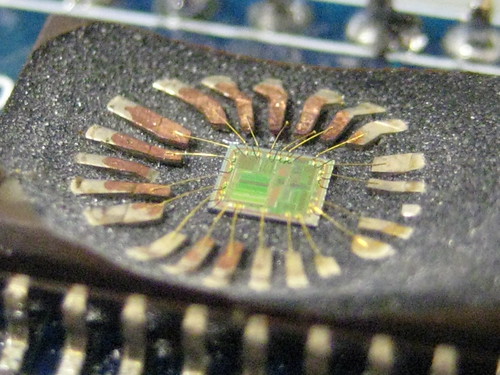
I've been playing lately with the use of light to induce temporary faults within a decapped MSP430F1101A. The chip, pictured above, was decapped by Chris of Flylogic Engineering. Lacking a convenient source of UV with which to begin erasing flash memory, I tried the flash from my digital camera. What luck!


Although it appears that flash memory has been reset, that is not in fact the case. The memory bus is paralyzed, with all reads returning 0xFFFF. This includes Flash, RAM, and ROM regions. After a while, this effect dissipates and memory returns to normal.

I'll soon begin to experiment with different wavelengths, durations, and polarizations of light. Please email me if you've any advice to offer.

Cheers,
--Travis

Saturday, August 16, 2008

Post-Vegas


Black Hat and Defcon were both a blast. My Black Hat slides and paper are available. See here for the book of which I spoke at Defcon.

Chris Tarnovsky of Flylogic Engineering let me photograph a run-through of the workshop that he later gave at Defcon. I've been locked out of my Flickr account, but you'll find most of those photos tagged with flylogic. I'll post the others if and when I recall my password.

It'll take me a while to send all the emails that I've promised. Please email me first if you have the time.

Cheers,
--Travis
<travis at utk.edu>

Monday, August 4, 2008

Vegas or Bust! Three talks in three days.

Howdy y'all,

I'm leaving Knoxville for Las Vegas in eight hours. I'll be speaking Thursday, Friday, and Saturday. Three talks, on three different topics.

Thursday/13h30 at Palace 1 in the Hardware track of Black Hat, I'll be speaking at Black Hat USA regarding a timing vulnerability of the MSP430FG4618's serial bootstrap loader. This is just after the lunch break. Come early to get a good seat, then keep it for talks by Karsten Nohl and Chris Tarnovsky.

Friday/16h00, I'll be speaking at Defcon 16 in the Breakout room regarding not my own work, but the historic work of Paul Courbis and SĂ©bastien Lalande. In 1990, they published «Voyage au centre de la HP28C/S» detailing the initial reverse engineering of the Hewlett Packard 28 graphing calculator. For the past year, I've been translating it as a hobby.

Saturday/18h00, I'll be giving a Defcon Skytalk on the topic of reverse-engineering an 802.15.4/Zigbee wireless sensor node using msp430static. This is a revision of my talk from Last Hope, with new content to reflect my Black Hat talk. I was added to the line-up at the last minute, so you won't find this in the conference booklet or the poster.

Please email me at the address below if you'd like to meet up.

Cheers,
--Travis Goodspeed
<travis at utk.edu>

Monday, July 28, 2008

Last Hope recap, slides

by Travis Goodspeed <travis at utk.edu>
at the Extreme Measurement Communications Center
of the Oak Ridge National Laboratory

Despite sleep deprivation and the longest drive of my life, I had a blast at the Last HOPE conference this past weekend.

You'll find the slides for my scheduled (Friday) talk at lasthope_goodspeed.pdf. Saturday's talk was a rerun from TIDC 08; thanks to Marco and Kevin Figueroa for getting me a projector on such short notice. Sunday's workshop was unrehearsed, and I apologize for not taking screenshots.

You'll find me next week at Black Hat 2008 and Defcon 16 in Vegas. In addition to my scheduled talks, I expect to give at least one unscheduled lecture or workshop during Defcon. Email me for details.

--Travis

Friday, July 4, 2008

Repurposing the TI EZ430U, Part 2

by Travis Goodspeed <travis at utk.edu>
at the Extreme Measurement Communications Center
of the Oak Ridge National Laboratory


EZ430 24c32 EEPROM Tap

Section 1, wherein topics of discussion are enumerated and datasheets cited.

The first installment of this series described a method of accessing the EZ430's MSP430 firmware by way of JTAG. That's dandy, but the MSP430 isn't the only microprocessor on the board! This installment will focus on the firmware and reprogramming of the TUSB3410 USB to serial chip, which contains an 8052 microprocessor core.

Section 11 of SLLS519 describes the boot sequence of the TUSB3410. In brief, an I2C EEPROM is used if such a chip is present and it contains an image with the proper signatures. Firmware may also be loaded over USB, in which case the EEPROM is either absent or provides only such minutia as the device ID.

The EEPROM on the Revision 2.0 boards--those with six pins for the target device--is the CAT24C32 by Catalyst Semiconductor. Revision 1.1 used the smaller CAT24C16 chip, presumably because that revision had no need for such complicated software. (See Part 1 for details.)

Section 2, wherein firmware is forcefully extracted by use of hypodermic syringe and our heroes contemplate an intriguing fragment of a schematic diagram.

The 24C32 chip, like all I2C devices, uses two lines for communication. These are SDA and SCL. Addressing lines, allowing for multiple units of the same chip to reside on a board, are unused and tied to ground. Thus, the chip looks something like the following schematic.

24c32 schematic

To read the chip, it is necessary to have an I2C host adapter, such as the Total Phase Aardvark. So as to avoid soldering headers to the chip, I attached two of my syringe logic probes to the Aardvark's SDA and SCL lines. Power was shared through USB, negating the need to tie it into the target board. I tapped an unlabeled via near R23 for SDA and tapped SCL directly on a leg of the EEPROM. I2C's multi-master feature allows this to be done without disabled anything in the board.

Section 3, wherein our heroes--having extracted the firmware of the 24C32 of the EZ430U--conspire to similarly free the firmware of an I2C EEPROM of a much finer vintage.

Dumping firmware from similar chips on the green EZ430U and a USB-FET gave samples for comparison. The contents of the green board and the FET were nearly identical, differing only by a few bytes. They are also significantly smaller than the red firmware, even though the FET contains a larger EEPROM. Unused bytes are padded as 0xFF.

The most common complaint regarding the EZ430-RF series is that, unlike the original EZ430, there exist no Linux drivers for the board. By reflashing the firmware of both the MSP430 and the 24C32 chips, a red EZ430 can be reverted to the green firmware, making it compatible with Linux.

For those without access to an I2C programmer, it is worth noting that the MSP430 of this board is tied to the 24C32 EEPROM. It is possible to write an MSP430 firmware image that, upon booting, does nothing but reprogram the TUSB3410's ROM.

Section 4, wherein your esteemed author prematurely concludes this article of the series.

The third installment contains instructions for compiling new firmware for the EZ430 by retargetting GCC and manually linking in the USB bootloader.

Thursday, June 19, 2008

Speaking at Last Hope

I'll be speaking at Last Hope in Manhattan next month. My abstract follows.

Introduction to MCU Firmware Analysis and Modification with MSP430static
The Texas Instruments MSP430 is a low-power, 16-bit microcontroller which is rapidly gaining in popularity in the embedded world. MSP430static is a tool for reverse engineering the MSP430's firmware. Following a quick tour under the hood of this tool, this lecture will demonstrate how to analyze, modify, and reflash a black-box firmware image.

The Last HOPE

Monday, June 16, 2008

MSP430 BSL Passwords: Brute Force Estimates and Defenses

by Travis Goodspeed <travis at utk.edu>
at the Extreme Measurement Communications Center
of the Oak Ridge National Laboratory
regarding the work of
Alexander Becher, Zinaida Benenson, and Maximillian Dornseif
with minor additions and comments.

The MSP430 microcontroller uses its 256-bit interrupt vector table (IVT) as a password for its serial bootstrap loader (BSL), which can remain activated despite a blown JTAG fuse. As code confidentiality then depends upon the BSL password, this article will make some preliminary observations as to the difficulty of guessing the password. It doesn't attempt to be terribly thorough, precise, or academic. Rather, consider this to be a few `back of the napkin' notes on breaking the password. Further, the scope of this article is limited to the brute forcing of passwords. Alternatives to brute forcing will not be discussed here.

A good starting point would be [1] Tampering with Motes: Real World Physical Attacks on Wireless Sensor Networks. It's an excellent paper, but be sure to get the 15-page version; the 4-page variant is no substitute. This article will begin by recapping their estimate of the BSL password strength, and it will conclude with the source code of a Perl script mentioned--but not included--in that paper.

The issue at hand is that the MSP430 reuses its interrupt vector table (IVT) as a password. Thus, while the password is technically 256 bits in length, many of those bits are either fixed or predictable. Further, as the BSL allows for direct memory access to the device, it might be used to compromise keys where the firmware is known.

Becher et all attempted to determine the minimum keyspace, which is to say the number of bits out of 256 which are truly unpredictable in a rather small program. Beginning with 256 bits in an array of sixteen 16-bit interrupt handler function pointers, their reasoning follows: (1) As all MSP430 instructions must be even-aligned, every valid interrupt handler must have a least-significant bit of 0. Therefore, the space is reduced to 16*15=240 bits. (2) As the reset vector always points to the beginning of flash memory, the space is further reduced to 15*15=225 bits. (3) All unused interrupts point to the same address. As a worst case would have at least four distinct handlers, the keyspace will be reduced to no less than 4*15=60 bits by this observation. (4) As code is placed in a contiguous region of memory, a smaller program would have less are in which to place interrupt handlers. Supposing the program uses only 2^11=2kb of flash memory, the key domain is reduced to only 4*10=40 bits.

Note that as the intent is to come up with a reasonable minimum, claims (3) and (4) above refer only to a reasonable minimum of program security. An average, complicated ZigBee application might well have many more bits of randomness. They then measured that the speed of a brute forcing algorithm is 12 passwords/second at 9600 baud, 31p/s at 38,400 baud, and 83p/s at 38,400 baud with a modified client. They state a theoretical limit at 38,400 baud of 150p/s. Rounding off to 2^7=128 passwords per second, they conclude that brute forcing would be limited to 2^(40-7-1)=2^32 seconds, which is roughly equal to 128 years.

I'd like to briefly consider how brute forcing might be sped up beyond their estimates, even if such a speed-up is not of sufficient magnitude to make unassisted brute-forcing of the BSL feasible.

While the most recent revisions of the BSL require a password for changing the baud rate, V1.60 and V1.61 have no such requirement[2]. When using this command, the BSL client sends three bytes: D1, D2, and D3. D3 is what we would expect: 0x00 for 9600 baud, 0x01 for 19200 baud, and 0x02 for 38400 baud. D1 and D2, however, are much more interesting. They are written directly to the clock module control registers! (DCOCTL and BCSCTL1 on F1xx/F2xx; SCFI0/SCFI1 on F4xx.) These two registers control the frequency of the device, and they may be set to anything the device supports, which is in excess of the 4.2Mhz required for 38400 baud. Further, bytes are read by bit-banging, which is calibrated by the 0x80 synchronization character. By sending 0x80 too quickly and setting the microcontroller to 8 or 16mhz, it should be possible to brute force at a much faster rate. 2^9 passwords is a reasonable rough estimate; a bit more might be possible. 32 years is still too slow to be practical, but perhaps with possession of another revision of the target firmware image this speed-up might be valuable.

Suppose that you wish to maximize the security of the BSL password on your MSP430-based device, and you don't want to disable the BSL entirely. Becher's solution from [1] is a Perl script which replaces each interrupt pointer in the IVT with a pointer to another address, which contains a branch to the original address. At the cost of a few extra cycles on each interrupt, it can considerably increase the difficulty of brute-forcing a password. Most importantly, by separately randomizing the vectors of every device you ship, it is possible to defend against an attacker who has a copy of the firmware but does not have internally held keys of a device from reading those keys through the BSL.

In August at Black Hat USA 2008, I'll be presenting a timing attack which makes it possible to break some revisions of the BSL in short order.

[1] Tampering with Motes: Real World Physical Attacks on Wireless Sensor Networks
[2] SLAA089: Features of the MSP430 BSL


#!/usr/pkg/bin/perl
use warnings;
use strict;

# Use with Intel Hex files for Texas Instruments MSP430 microcontrollers.
# Replace ALL interrupt vectors with addresses generated randomly.
# Store jump instructions to the original interrupt handlers there.

# Written by Alexander Becher <alex@cyathus.de>, 2005.
# Use freely.

# $start and $end define the address range into which new vectors will point.

# The start address will be updated by the Ihex reading code below.
# It must be correctly aligned.
my $start = 0x4000;

# This is where the interrupt table starts. Addresses >= $end will not be used!
my $end = 0xffe0;

my $align = 2; # code addresses on MSP430 must be even

my %used; # will contain used memory regions

my @interrupts; # stores the original interrupt vector table

# Read an Intel hex file. With much help from BFD.
while (<>) {
my ($len, $addr, $data, $checksum)
= (/^:([[:xdigit:]]{2})([[:xdigit:]]{4})00([[:xdigit:]]*)([[:xdigit:]]{2})\cM?$/);

## Does not work? What did I do wrong??
# if (m/^: # colon
# ([[:xdigit:]]{2}) # data length
# ([[:xdigit:]]{4}) # address
# 00 # record type
# ([[:xdigit:]]*) # data
# ([[:xdigit:]]{2}) # checksum
# \cM?$/x # CRLF
# ) {

if (!defined $addr || ($addr ne "FFE0" && $addr ne "FFF0")) {
# update start of unused address region
# assume ascending order of addresses
# (i.e. it is not the case that there is a line in the hex file
# which contains code for address 0x4242 which is followed by a
# line which contains code for address 0x2323)

# assume all data first, then interrupts, then trailing stuff
if (defined $addr && defined $len) {
$start = align(hex($addr) + $len);
}

print;
next;
}

# If we reach this point, we are reading the first or the second
# line of the interrupt vector table.

# Attention: MSP430 is little endian!
while ($data =~ /([[:xdigit:]]{2})([[:xdigit:]]{2})/g) {
push @interrupts, hex "$2$1";
}

# If this is the second line, do The Real Work[tm].
if (@interrupts && $addr eq "FFF0") {
replace_interrupts(@interrupts);
}
}

#
# Why this program exists ;->
#
sub replace_interrupts {
my (@interrupts) = @_;

foreach my $addr (@interrupts) {
# Create a branch instruction to the original address of the handler
my $instr = br($addr);

# Get a new, unused address, using key material
my $new_addr = new_addr(length $instr);

# write a branch instruction there, mark appropriate addresses as used.
code($new_addr, $instr);

# point interrupt vector to new address (use Perl's loop aliasing)
$addr = $new_addr;
}

print ihex(0xFFE0, map { rep_16bit_le($_) } @interrupts);
}

#
# Returns a new random unused address suitable for putting code of
# $length bytes there. Return value will be aligned.
#
sub new_addr {
my ($length) = @_;

my ($addr, $diff);

$diff = ($end - $start) / $align;

# create a new random address until an unused region of the desired
# length is found
do {
my $n = int rand $diff;
$addr = $start + $n * $align;
} while (grep { $_ } map { isused($addr+$_) } (0..$length-1));
# Woohoo, Perl's list processing rocks. ;-> The above was a crude
# form of "Is any address in the region [$addr, $addr+$length) used?".

return $addr;
}

sub isused { $used{shift()} }

sub mark_used {
my ($addr, $len) = @_;

foreach ($addr .. $addr + $len) {
$used{$_} = 1;
}
}

#
# Place $code at $addr (which must be aligned). Outputs an ihex line
# which says just that, and marks the memory area as used.
#
sub code {
my ($addr, $code) = @_;

my $l = length $code;
mark_used($addr, $l);

print ihex($addr, $code);
}

# MSP 430 branch instruction
sub br { "\x30\x40" . rep_16bit_le(@_) }

# 16 bit little endian representation
sub rep_16bit_le { pack("v", @_) }

# ihex($addr, @data)
# write an ihex line, saying that $addr contains bytes @data
# @data should contain "\xXX" binary data
sub ihex {
my ($addr, @data) = @_;

@data = split //, join("", @data);

my $type = 0; # data

my $ret = "";

while (@data) {
my @bytes = @data >= 16 ? (splice @data, 0, 16) : (splice @data);

my $c = @bytes;

# XXX pack?
my $data = join("", map { sprintf "%02X", ord $_ } @bytes);

# checksum computation from GNU binutils bfd/ihex.c
my $checksum = $c + $addr + ($addr >> 8) + $type;
foreach (@bytes) {
$checksum += ord;
}
$checksum = (- $checksum) & 0xff;

$ret .= sprintf(":%02X%04X%02X%s%02X\cM\cJ",
$c, $addr, $type, $data, $checksum);

$addr += 16; # wrong for last iteration, but irrelevant then
}

return $ret;
}

# round up to the nearest multiple of $align
sub align {
my ($n) = @_;
if ($n % $align != 0) {
$n += $align - ($n % $align);
}
return $n;
}

Sunday, June 15, 2008

Syringe Logic Probe, Revision 2


While my original probe is damned useful, it was a bit of a rushed job. Since then, I've found uncoated silver jewelry wire whose diameter is just a hair smaller than the inner diameter of the needle, allowing me to force it in for an electrical connection. More importantly, as I no longer solder to the outside of the needle, I can restore the safety cap and save my fingers from getting nicked.

--Travis Goodspeed
<travis at utk.edu>

Friday, June 13, 2008

Spring Cleaning

microbox contents
I just received Nick Chernyy's Microbox as part of The Great Internet Migratory Box of Electronic Junk project.

I took the 8051 board, the 2x16 LCD, and a MAX232 level-converter chip. I then removed a healthy number of packing peanuts, swapped one of the microcontroller cases for a smaller one, and added the following:
  • Two PICs.
  • Three MSP430F2012 DIPs.
  • A 4G iPod, sans hard disk
  • Two TI CC1100 radio boards.
  • A board of ZIF sockets for PIC programming.
As is tradition, I'll be sending the box to someone on the Box Requests page within the next week or so.

--Travis

Monday, June 2, 2008

CopyWench, a File Format for Publicly Discussing Undistributable Material

by Travis Goodspeed <travis at utk.edu>
at the Extreme Measurement Communications Center
of the Oak Ridge National Laboratory

Suppose that an author has written a document describing the reverse engineering of ROM image, and he wishes to publish his work. Further, let us suppose that the author is an honest and law-abiding citizen of a nation with intellectual property laws that prevent him from distributing software copyrighted by another. He cannot distribute his work in its entirety, as his work will cite numerous lines of the original. In this short article, I will discuss a format for a utility which--much like diff--allows an author to distribute only his changes to a document. Unlike diff, my format will not include so much as a single line of the original.

First, suppose this to be our secret file. It is from Wikipedia's BASIC article. We'll call it secret.txt:
10 INPUT "What is your name: ", U$
20 PRINT "Hello "; U$
30 INPUT "How many stars do you want: ", N
40 S$ = ""
50 FOR I = 1 TO N
60 S$ = S$ + "*"
70 NEXT I
80 PRINT S$
90 INPUT "Do you want more stars? ", A$
100 IF LEN(A$) = 0 THEN 90
110 A$ = LEFT$(A$, 1)
120 IF A$ = "Y" OR A$ = "y" THEN 30
130 PRINT "Goodbye ";U$
140 END
Each line of secret.txt has a one-way MD5 hash, which is what will be published in lieu of the line itself. To someone who does not have the secret file, 12b9bdf57db1a1c9e4fb2fb1b35e9c41 means nothing. But to someone who does have the file, it's rather easy to find that the hash belongs to line 10 above.

Suppose this to be our private commentary:
Commentary of a BASIC program.
by John Doe.

10 INPUT "What is your name: ", U$
My name is John!
20 PRINT "Hello "; U$
Hello to you, too!
30 INPUT "How many stars do you want: ", N
Tons of stars!
40 S$ = ""
50 FOR I = 1 TO N
60 S$ = S$ + "*"
70 NEXT I
80 PRINT S$
90 INPUT "Do you want more stars? ", A$
Always.
100 IF LEN(A$) = 0 THEN 90
110 A$ = LEFT$(A$, 1)
120 IF A$ = "Y" OR A$ = "y" THEN 30
130 PRINT "Goodbye ";U$
Adieu.
140 END
By replacing every secret line--that is to say every line which is found in secret.txt--with a one-way hash of the original, we will arrive with something like the following, which is free of copyrighted material.
Commentary of a BASIC program.
by John Doe.

COPYWENCH 12b9bdf57db1a1c9e4fb2fb1b35e9c41
My name is John!
COPYWENCH 8a80ddc83dc0592951d29151d62487a4
Hello to you, too!
COPYWENCH cbbf650ae187427f3cd74a58a7b0edf4
Tons of stars!
COPYWENCH f842a481f76099503c63c611dc84784e
COPYWENCH 9376ab1f0bed02260134dc9d6b723433
COPYWENCH 5cbb0ef3dbb1b75c047b278b3480fa46
COPYWENCH 95cfeba9a3004c3e6b2db6ce3222341b
COPYWENCH 402c331f990b99054568e72315e5e01b
COPYWENCH f8ee49bfcd41e6a43266105e65964247
Always.
COPYWENCH 24407c853d6df83fecd3074dc44e5ef5
COPYWENCH cc67be8c43810e63859ae75abaf7b1c2
COPYWENCH 36c25fd5bf40b1a5a0ef8d68af1580c7
COPYWENCH 80a1d74d3d5b1321fe3805a6d6f6011c
Adieu.
COPYWENCH 811061ce8478b3e56543e103ccd52c67
The following algorithm will translate between public and private files:
  1. For each line of secret.txt:
    1. Place a hash of the line in an associative array.
  2. Then for each line of the input file,
    1. If the line begins with COPYWENCH, print the line matching the checksum of the second word.
    2. Else if the line exists in the associative array, print "COPYWENCH" followed by a space and the line's hash.
    3. Else print the input line.
I recommend this file format, which I've named the CopyWench format, because it is terribly easy to implement. A few minutes in any scripting language will result in a working implementation.

A sample implementation follows. As all implementations ought to be licensed so as to be distributable with the documents with which they are intended to be used, this one is in the public domain. Do with it as you will.

#!/usr/bin/perl

#CopyWench 0.1
#Authored for the Public Domain
#by Travis Goodspeed <travis at utk.edu>

#Either Digest::MD5 or Digest::Perl::MD5 is needed.
BEGIN {
eval {
require Digest::MD5;
import Digest::MD5 'md5_hex'
};
if ($@) { # no Digest::MD5
require Digest::Perl::MD5;
import Digest::Perl::MD5 'md5_hex'
}
}

if($#ARGV!=0){
print "Usage: $0 secret.txt <input.txt >output.txt
Where secret.txt is the secret being written about.\n"
;
exit;
}

my $secret=$ARGV[0];
my %lines;
my ($line,$hash);
open SECRET, "<$secret";

#Build an associative array of secret lines.
while(<SECRET>){
chomp($_);
$line=$_;
$hash=md5_hex($line);
#print "$hash $line\n";
$lines{$hash}=$line;
}
close SECRET;

while(<STDIN>){
chomp($_);
$line=$_;
$hash=md5_hex($line);
if($lines{$hash}){
print "COPYWENCH $hash\n";
}elsif($line=~m/\bCOPYWENCH ([0-9a-f]+)/){
print "$lines{$1}\n";
}else{
print "$line\n";
}
}

Thursday, May 29, 2008

Speaking at Defcon 16

After Black Hat, I'll be speaking at Defcon 16 regarding an entirely different subject. The abstract follows.

In 1990, a wire-bound book was published in Paris by the title of «Voyage au centre de la HP28 c/s». It presents a very thorough account of the inner workings of the Hewlett Packard 28 series of graphing calculators. Designed before the days of prepackaged microprocessors, the series uses the Saturn architecture, which HP designed in-house. This architecture is very different from today's homogeneous RISC chips, with registers of 1, 4, 12, 16, 20, and 64 bits in width. The fundamental unit of addressing is the nibble, rather than the byte. Floats are represented as binary-coded decimal, and a fundamental object in the operating system is an algebraic expression.

This architecture is still used, albeit in emulation, in the modern HP50g. With this talk, I intend to call attention to a fascinating, professional, and well-documented feat of reverse engineering. Using little more than their ingenuity and an Apple ][e, Paul Courbis and Sebastien Lalande reverse engineered a black box calculator into a real computer, one which became user-programmable in machine language as a result. More than that, they documented the hack in such exquisite detail that their book is not just a fascinating read, but also veritable holy scripture for anyone trying to write custom software for this machine.

Expect a thorough review, in English, of the contents of the book. This is not a sales pitch; electronic copies of both the translation and the original are free to all interested readers. Topics include the datatypes of the computer algebra system, hacking an upgrade into the memory bus, bootstrapping an assembler, writing in machine language by tables, and adding an I/O port for software backups.


If you'd like a copy of the book in advance, grab the original French from the site of Paul Courbis or email me for a rough draft of the English translation.

--Travis Goodspeed
<travis at utk.edu>

Sunday, May 18, 2008

Repurposing the TI EZ430U, Part 1

by Travis Goodspeed <travis at utk.edu>
at the Extreme Measurement Communications Center
of the Oak Ridge National Laboratory

JTAG port

Lately I've been playing with the EZ430U, which is the adapter that ships with the TI EZ430 kits. The kits are an amazing deal, $20 gets you a spy-bi-wire MSP430 FET, while $50 gets you a similar FET with two wireless sensor nodes. Page 13 of SLAU227 contains the schematic diagram for Rev 2.0 of the MSP430U board, which ships packages as both the classic EZ430f2013 and the new EZ430rf2500; the only hardware difference is the color of the board, being green or red respectively.

The software differences, however, aren't so forgiving. While the classic kit readily creates a USB->serial device under Linux, the RF kit is as yet unusable in Linux as the interface was altered to support a second serial line, one to target board.

Each kit is composed of two types of boards, a programmer (EZ430U) and a target (RF2500T or T2012). While the target boards are a lot of fun, an email I received after my initial release of msp430static introduced me to something just as fun. Namely, the JTAG fuse of the EZ430U board is left unblown. The following diagram shows pin connections from the row of 5 testpoints on the side of the board.

The lack of a common ground is no problem, as ground and power both come from the same computer through USB. You'll need a proper JTAG FET; another EZ430 won't do. (The EZ430 programmer only supports spy-bi-wire; it cannot program traditional JTAG boards.)

Having ripped the firmware from both the RF kit and the 2013 kit, I thought it might be interesting to compare the two. For a brief visual comparison, consider the following memory maps. The first is of an EZ430U from a classic 2013 kit, the second is of the EZ430U from an RF kit.
ez430u memmap ez430urf memmap
Taking the difference of the two images yields
ez430u memmap diff
The lowest bands of the image, being ram and I/O, ought to be ignored. Still, higher memory makes it visually clear that the firmware images are different. Comparing library checksums confirms this: few functions are identical between the two revisions.

The RF firmware reports itself to the USB controller as "0451:f432" while the classic board reports itself as "0451:f430". The identification appears must reside in the ROM of the 3410 chip, as the RF variant identifies itself as f432 even when loaded with the classic variant's firmware.

The second installment of this series continues with details of the TUSB3410 firmware, which resides on an EEPROM.

Friday, May 16, 2008

Speaking at Black Hat USA 2008

I'll be speaking at BlackHat USA 2008 in Vegas this August. My abstract follows:

The Texas Instruments MSP430 low-power microcontroller is used in many medical, industrial, and consumer devices. It may be programmed by JTAG, Spy-Bi-Wire, or a serial BootStrap Loader (BSL) which resides in masked ROM.

By design, JTAG may be disabled by blowing a fuse. The BSL may be disabled by setting a value in flash memory. When enabled, the BSL is protected by a 32-byte password. If these access controls are circumvented, a device's firmware may be extracted or replaced.

After a thorough introduction, this talk will discuss in excruciating detail the results of an effort to reverse engineer the BSL code. Once the BSL's function has been covered, a timing attack will be discussed which might be used to guess the password without brute force under certain conditions.


Cheers,
Travis Goodspeed
<travis at utk.edu>

Thursday, May 15, 2008

Syringe Logic Probe

I hope my faithful readers will forgive a quick detour into electronic arts-n-crafts. Rest assured, I won't abandon assembly language to make toilet-paper covers and tea cozies. Instead I intend to demonstrate how a diabetic MacGyver would tap a difficult pin on a circuit board.

After building Sump's Logic Analyzer out of a spare Spartan 3 board, I needed a logic probe with a sharp tip. What's sharp enough to grab a pin on a QFP device or those microscopic columns of solder that are exposed around the perimeter of a QFN device? An insulin syringe, of course!
syringe probe
The tip is razer sharp, easily digging far enough into a pin to hold its place. A finger's weight on the plunger keeps the probe in place; it has never once slipped to short two pins, as my multimeter's probe is wont to do.
closeup of syringe tip
I haven't yet tested the probe's electrical properties at high frequencies, but it works well enough for sniffing AES keys from an SPI bus.


Cheers,
--Travis Goodspeed
<travis at utk.edu>

Saturday, April 26, 2008

MSP430 Side-Channel Timing Attacks, Part 1

by Travis Goodspeed <travis at utk.edu>
at the Extreme Measurement Communications Center
of the Oak Ridge National Laboratory

regarding ongoing work performed in collaboration with
David Carne <davidcarne at gmail.com>

What follows is a brief introduction to microcontroller side-channel timing attacks, as one might find them on the MSP430 microcontroller. This sort of attack is most commonly used against cryptography, but my present discussion will focus on attacking password-comparison routines. Be sure to check your own code--as well as that of your library vendors--for this issue.

Suppose that a password protection routine accepts a password through the serial port from an untrusted source, compares the password, and raises the privilege level if the password is correct. We will consider the following attempts at implementing such protection.

strcmp

Using strcmp() is clearly not a secure option, because it leaks information. Let us consider the implementation from the strcmp article at Wikipedia.
int strcmp (const char * s1, const char * s2){
while ( *s1 == *s2 && *s1 != '\0' ) {
s1++;
s2++;
}
return *s1 - *s2;
}
This function--when used to compare passwords--runs in linear time, which is to say that every correct letter of the password adds a constant amount of time to the function's execution. By measuring the time that it takes to return, an attacker can guess the password one byte at a time. So an attacker could guess a 32-byte password in at most 32*256=8192 attempts, instead of the 2^^(8*32) attempts that might naively be assumed.

Another Attempt

Aversion to the C string comparison function is often enough to prompt authors to come up with creative comparison methods. One vendor uses a scheme similar to the following:
  • An access control variable is set to 1.
  • For each input byte:
    • The input byte is compared to the matching byte of the password.
    • If the two differ, the access control variable is cleared.
  • Access is granted if the access control register is still set.


The center of this loop, if isolated to be a function, looks something like this:
void check(char a, char b){
if(a!=b)
access=0;
}
When compiled to assembly language with GCC, the result is the following:
    c040:       4d 4f           mov.b   r15,    r13     ;
c042: 4d 9e cmp.b r14, r13 ;
c044: 02 24 jz $+6 ;abs 0xc04a
c046: 82 43 22 02 mov #0, &0x0222 ;r3 As==00
c04a: 30 41 ret
Which has the following flow diagram:

Even though the password comparison is now independent of length, there is a still a variance in timing. Every incorrect byte of the password will add four cycles of execution time to the comparison! To fix this, it's necessary to make an else{} clause which balances the timing.

In practice, it's often only possible to determine whether a guess regarding timing is correct or incorrect. This is done by "gambling a clock edge", using non-standard timing in a serial protocol such that an edge is detected under one timing but not detected in another. Using this technique, the worst-case time for guessing is the same as the strcpy() example.

The possibility remains, however, that still more information may be leaked. In such a case, because all bytes are compared, it might be possible to break the password in significantly fewer attempts. The fastest cracking case would be one in which each byte's correctness could be individually determined, in which case the password could be guessed in 256 attempts.

Balanced Timing

A proper password comparison ought to look like the following, which takes the same amount of time to execute, regardless of the password's correctness.

Proper support for automated timing analysis isn't yet available in msp430static, but its insflow() sub--which was used to generate the diagrams above--does a lot of the work. To reproduce these diagrams, dump the flow graph to disk then annotate timing to match the Instruction Timing section of the mspgcc manual or the Instruction Cycles and Lengths subsection of the Instruction Set section of an MSP430 family guide. The Single Line MSP430 Assembler is also handy.

I'll be writing more on this topic in the near future, perhaps citing some examples of this vulnerability that I've located in the wild.

Saturday, April 12, 2008

MSP430static Blog

I commit a lot of changes to msp430static, and I'd rather not flood this blog with posts describing every significant commit. For that reason I've created the MSP430static Blog to detail the changes.

--Travis

Wednesday, March 26, 2008

Speaking at Toorcon Seattle, Twice

On April 18th, I'll be speaking at Toorcon Seattle at 8:35pm regarding a traffic light controller's firmware.
Inside a Traffic Light Controller's Firmware
The Econolite ASC/3 is a black-box device that manages traffic and pedestrian cross-walk lights. Having been given a unit and instructions to make it programmable from Matlab, I did what any self-respecting engineer would do. Namely, I disassembled its firmware, identified its checksumming algorithm, and mapped the relevant bytes of its file format. A bit of XML magic later, and I had a library for reading, writing, and signing configurations. This brief talk will discuss my adventure. It will not discuss forcing a green light or similar tomfoolery.

The following afternoon at 2:40, I'll be speaking at the same conference regarding msp430static.
Homegrown Analysis Tools for 16-bit Microcontroller Firmware
16-bit architectures are a playground for analysis tool developers. This talk will cover the author's development of a reverse-engineering tool for the MSP430. Both the tool and this talk feature function isolation, recovery of stripped symbol information, call-graph generation, simulation, and scripting. Rather than focusing on the usage of the tool, the intent of this talk is to demonstrate how members of the audience might write their own. Source code will be available online, and a personal walkthrough of the code will be performed during the Q&A session for those that are interested.

ImageCraft and AS430 Library Formats for the MSP430

by Travis Goodspeed <travis at utk.edu>
at the Extreme Measurement Communications Center
of the Oak Ridge National Laboratory

I've been playing with various MSP430 compilers lately in an attempt to add import macros to msp430static. GNU's objdump makes this trivially easy for mspgcc, but I haven't been so lucky with the other compilers. One exception is ImageCraft's compiler, whose library format is beautifully manageable. This short article will discuss that format, with sufficient depth that a decoder or encoder script may be written. I will also discuss another tool, the AS430 assembler, which uses a similar file format.

A free 4kb version is available at http://www.imagecraft.com/. It works perfectly in Linux, just run `wine iccv7430_demo.exe', installing it to /opt/iccv7430/. Once installed, the IDE can be launched by `wine /opt/iccv7430/bin/icc430ide.exe'.

The following image shows the opening lines of libc.a, which is in a relocatable object format similar to that of the AS430 linker's.

You can find a description of the linking format, here.

The S-line tells us that the object's symbol name is _abs. The T-line contains the object code, "00 00 0e 93 03 34 3e e0 ff ff 1e 53 30 41". This R-line specifies no relocation.

The code, which begins at the third byte of the T-line, disassembles to the following in word-wise notation:
0x930E cmp #0, r14
0x3403 jge +8
0xE03E XOR #0xFFFF,r14
0xFFFF
0x531E add #1, r14
0x4130 ret

Quite obviously, this inverts and adds 1 to r14 if its value is less than 0. In C,
int _abs(int x){
if(x<0)
return -x;
else
return x;
}
It's worth noting that r14 can be inverted with a single word, 0xE33E, rather than the two used here by use of the constant generator. That is exactly what GCC does:
   0:   0f 93           cmp     #0,     r15     ;r3 As==00
2: 02 34 jge $+6 ;abs 0x8
4: 3f e3 inv r15 ;
6: 1f 53 inc r15 ;
8: 30 41 ret
Getting back to the format at hand, AS430 may be downloaded here. Go for the latter link, as it's direct and doesn't require that you run Simtel's win32 downloader application.

Once downloaded, Linux users should install by use of the following commands:
karen% sudo ln -s `pwd`/ASXMAK/LINUX/EXE/AS430 /usr/local/bin/as430
karen% sudo chmod +x ASXMAK/LINUX/EXE/*
karen%
Moving the T430.ASM example to T430.asm, calling "as430 -o T430" creates T430.rel, in the same relocatable object format used above. It's rather inconvenient that the tool is case-sensitive and windows-oriented, but it works well in Linux once you recognize its difficulty with case-sensitive filesystems.

Object division is different in ImageCraft. Note the ^M entries in the screenshot, which in emacs denote a CR. The entries only exist between the .begin/.end macros, suggesting that the file was produced with more than one tool. This makes sense: one tool is the archiver, while the other is the assembler. The archiver uses LF, as in Unix textfiles, while the assembler uses CRLF, as in DOS textfiles.

Just to be sure this would ship in production code, I used abs() in an example project and found the following in the output ihex:
:14F064000495FD3B30410E9303343EE0FFFF1E53304130410
'3EE0FFFF' is the little-endian equivalent of '0xE03E 0xFFFF' above.

Some other formats, all of them ASCII, deserve mention here. The first being the debug format, which is built into PROJECT.dbg by the IDE.
IMAGECRAFT DEBUG FORMAT
VERSION 1.2
CPU MSP430
FRAMEPOINTER R1
DIR z:\home\travis\tmp\icc\
FILE foo.c
FUNC main F052 fV
BLOCK 3 F052
DEFREG x 5 I
DEFREG y 4 I
LINE 3 F052
LINE 4 F052
LINE 5 F05E
LINE 6 F060
LINE 6 F062
LINE 6 F062
LINE 6 F064
BLOCKEND 0 F068
FUNCEND F068
FILE foo.s
LINE 16 F052
LINE 17 F056
LINE 18 F05A
LINE 19 F05C
LINE 22 F05E
LINE 25 F060
LINE 30 F062
LINE 33 F064
LINE 34 F066
LINE 38 F068
START F000
This is easy enough to read. FILE defines a source file, FUNC defines a function, BLOCK defines a region of code, DEFREG defines which register a variable is contained within, and LINE denotes the address to which a particular line has been compiled.

PROJECT.lst contains annotated machine code. PROJECT.mp describes memory areas and linking information.

PROJECT.mak is a makefile. Building from the command-line works perfectly with the proper environment variables, but without them the unregistered version will refuse to run outside of the IDE.
karen% wine /opt/iccv7430/bin/imakew.exe -f FOO.mak 
icc430 -c -IC:\icc\include\ -e -D__ICC_VERSION="V7.06A" -DF148 -l -g -Wf-hwmult -Wa-g z:\home\travis\tmp\icc\foo.c
icc430 -o FOO -LC:\icc\lib\ -g -blit:0xF000.0xFFDF -bdata:0x0200.0x0A00 -dram_end:0x0A00 -fintelhex -binfo:0x1000 @FOO.lk
Device 3% full.
karen%
I like the ASCII nature of the compiler's file formats, which makes them very easy to parse. For this reason, the compiler was the first after GCC to be supported in msp430static.

Wednesday, March 19, 2008

Speaking April 4th at UT, Knoxville

I'll be repeating my Texas Instruments Developer Conference talk in room 206 of Claxton Hall at the University of Tennessee, Knoxville on Friday, April 4th from five to seven o'clock for the local chapter of the ACM. The abstract follows:
Stack Overflow Exploits for Wireless Sensor Networks Over 802.15.4

Stack overflows have been a threat to security since the early 1980s,
but developers consistently leave such vulnerabilities open to attackers
because of mistakes in boundary checking. These mistakes are quickly
found and either fixed or exploited on servers and personal computers.
In industrial embedded systems, however, they are often left in deployed
products because of high replacement costs and the perceived difficulty
level of an attacker reaching the deployed system. IEEE 802.15.4,
Zigbee (R), ISA100 and wireless sensor networks using these protocols
are fertile ground for such exploits. This presentation presents an
application-layer protocol implementation that is vulnerable to a buffer
overflow, showing step-by-step how an attacker could write an exploit
that injects and executes arbitrary machine code over the air -- and how
you can prevent such an attack. The target system is a Telos B wireless
sensor node running TinyOS 2.x on the TI MSP430 microcontroller with a
TI/Chipcon CC2420 radio.
Please email me, travis at utk.edu, if you are interested in attending a hands-on workshop later that evening.

Monday, March 17, 2008

ImageCraft V7 Symbol Importing for MSP430static

by Travis Goodspeed <travis at utk.edu>
at the Extreme Measurement Communications Center
of the Oak Ridge National Laboratory

I just committed r38 of msp430static which adds support for importing symbols from ImageCraft V7 for MSP430. A short example follows.

I'll use the following C code, but any will suffice.
void main(){
int x=0xFFFF;
x+=1;
x+=0xFFFF;
x+=abs(5);
}
Compiling it yields many files. The two of interest are FOO.hex and FOO.mp. The former is imported by converting it to msp430-elf and dumping the resulting ELF file.
karen% msp430-objcopy -I ihex -O elf32-msp430  FOO.hex foo.exe
karen% msp430-objdump -D foo.exe | m4s init
karen%
Symbols are then imported with the .symbols.import.ic7 macro.
karen% m4s .symbols.import.ic7 <FOO.mp
karen%

At this point, msp430static knows the name of every function in my image. Here is the callgraph of my program above.


Note that my examples are in Linux. ICC 7 works perfectly as both an IDE and compiler under Wine.