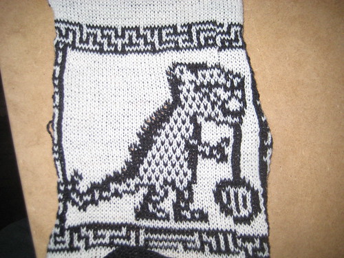
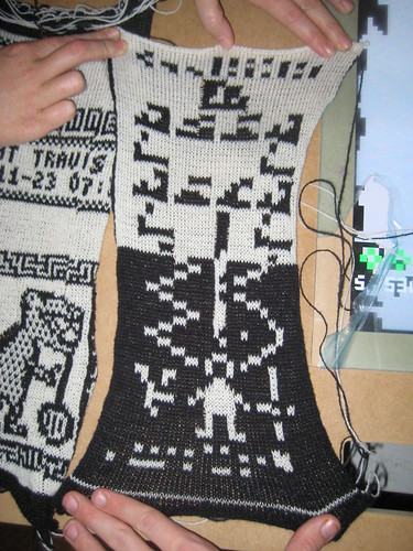
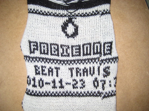
in collaboration with Fabienne Serriere and Arjan Scherpenisse,
at Mediamatic's RFID Devcamp 2010, Amsterdam,
for Multithreaded Banjo Dinosaur Knitting Adventure 2D Extreme,
with kind thanks to David Carne.
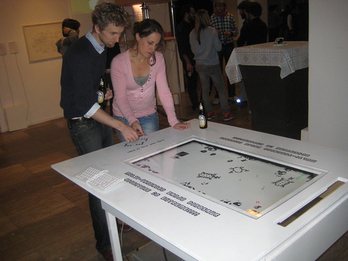
Thanks to some extra-neighborly blackmail by Fabienne, I spent last week hacking up a storm in Amsterdam. By extending the work of Steven Conklin, Limor Fried, and Becky Stern, we were able to hack a Brother KH930 knitting machine to print high score panes from a custom video game in yarn. This game was then displayed at Mediamatic for SensorFest, leading all sorts of neighbors to learn that RFID, socializing, and beer can lead to a neighborly time. Never in my life did I expect to get such an adrenaline rush from knitting, much less from from this newfangled social networking nonsense.
Conklin's technique for loading new patterns into the machine involves using an FTDI chip to simulate a Tandy PDD1 floppy disk drive, then typing "CE 5 5 1 STEP 1 STEP CE STEP STEP CE 9 0 3 STEP STEP" to load a new pattern set from disk and print pattern 3 of the set. (551 is the command to read from disk, and patterns held in RAM begin at 900.) For our exhibit, this sequence was far too complicated to type for every half meter of output, so we hacked the device's keypad for scripting.
This article describes how a matrix keypad works, how we reverse engineered the specific keypad of the Brother KH930, and how to use an Arduino with a handful of transistors to automate the typing of commands necessary for loading a new pattern from an emulated floppy disk. It should be applicable to all sorts of keyboards, but for those with serial protocols there might be a simpler method.
Unfortunately, there won't be room here to describe the first emergency knitting machine purchase in history, our A-Team trip to the far side of Holland in a borrowed van, or the case of Club Mate that we begged from a squatter bar in order to finish the project in the five days allotted.
A keypad matrix is most often built with switches that connect a row wire to a column wire. By keeping every column in a high-impedance state with pull-up resistors, then dropping each row low in sequence, the column inputs can be sensed to determine when a button is pressed. Dave's Hacks' first article on IM ME Hacking describes in detail how the keypad of the GirlTech IMME works, and all other implementations seem to function similarly.
The connections between rows and columns are just switches.

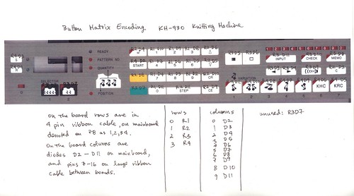
While in a perfect world, rows and columns would be arranged exactly as they appear visually, this is rarely efficient to route in copper for more than twelve buttons. We produced the diagram below by scanning the keyboard membrane, then pushing a button while using the continuity tester to see which row and column wire were connected. The table at the bottom converts from wire signal names to the Arduino signal names used within the client library.
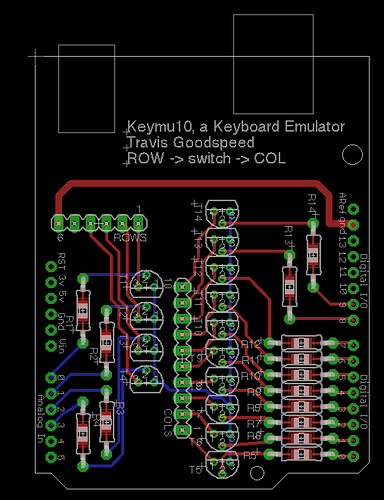
In order to connect rows and columns to a center rail, I used BC547 NPN transistors prototyped on an Arduino shield. Each has a 1K resistor on the base. Row transistors have the collector coming from the row signal and the emitter going to the common rail; column transistors are the same, except that the collector and emitter are swapped in order to fit the direction of current.
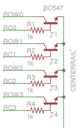
As each transistor conducts when only when its base is high, the Arduino can press a key by first dropping all outputs low, then raising a row control line (RCx) and a column control line (CCx) high. Because of debouncing and a limited scan rate, this must be held for a short amount of time before releasing the key.
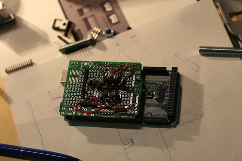
Such a design fits perfectly well on a prototyping shield, although the transistors are a tight fit. I recommend first prototyping a single row and column to ensure that the transistors are properly aligned, as current direction might be different on your keypad.
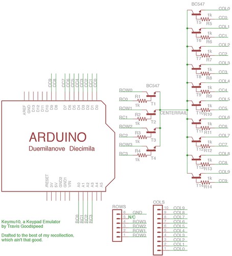
For those who prefer to have a board fabbed, here's a proper schematic and layout. Gerbers and Eagle CAD source files are available in the project's subversion repository.
A more sophisticated software implementation would involve using the Arduino's serial port to communicate with the host, accepting strings in ASCII and translating them to keypresses. We decided against such a complication because we feared relying on a second long USB cable. Further, we thought it handy when necessary to be able to run the device stand-alone with a single (reset) button press from the operator signaling that the next pattern should be loaded.
Full keyboard emulator code is available either by pastebin or from SVN. You'll find it in banjo/code/arduino.
svn checkout svn://svn.mediamatic.nl/devcamps/camp10/banjo
The code works by using simple methods to press a row and column by raising those pin voltages. Higher level methods allow for such functions as loading a pattern from disk or printing a pattern, each by performing multiple key presses and occasionally inserting a delay. By placing this within the Arduino code's setup() function, the pattern is loaded whenever the device is reset.
New patterns are loaded from the Banjo Dinosaur Knitting Adventure 2D Extreme game by first starting a floppy disk emulator--as per Steve Conklin's technique--then pulsing the DTR line of the arduino in order to cause a reset. The Perl for that is just a single line,
Device::SerialPort->new("/dev/ttyACM0")->pulse_dtr_on(100)
The end result, with a machine typing by itself, looks a little like this,
That's all there is to it. With fourteen transistors and just as many resistors, you can script your knitting machine--or any other keypad device--from a microcontroller without modifying the underlying firmware.
As a final note, I will give a cookie to the first neighbor who uses this technique to dump all of the power codes from a universal infrared remote control, or to program something long and sophisticated into a graphing calculator that lacks a link port.
