Wednesday, October 28, 2009

MSP430 Info Flash

by Travis Goodspeed <travis at radiantmachines.com>

The following is a description of the MSP430F2xx Info Flash, as well as my ugly--yet reliable--hack for initializing the DCO of MSP430F2xx chips after my use of the Serial Bootstrap Loader (BSL) has destroyed the contents of that flash on the GoodFET. This ought to be of use to anyone who wishes to make an MSP430 design without a crystal, as well as for anyone who has accidentally erased info flash.

The mask-ROM bootstrap loader, BSL, of the MSP430 chips is damned handy, despite some security concerns. It allows you to very quickly program a chip by the same USB/serial converter that you use to interface it with a computer, without any of the hassles of having to flash a bootloader onto the chip. In this article, I describe the way in which the MSP430F2xx flash can be accidentally corrupted by the bootloader, as well as a method for repairing that damage by backing up the info flash while the password is left as the default.

The MSP430F2xx family has another dandy feature, that clock configuration values need not be calibrated to an external clock, such as the 32KHz crystal of the older GoodFET models. Instead, configuration data is calculated at the factory and placed into info1 flash, a region of 256 bytes at 0x1000. Using this, code that would be rather complicated can become trivially simple.

The code that configures the clock is configured on the GoodFET with MSP430F1xx chips is too complicated for me to include here. By contrast, on the MSP430F2xx chips, it becomes just
void msp430_init_dco() {
BCSCTL1 = CALBC1_16MHZ;
DCOCTL = CALDCO_16MHZ;
}


The security model of the BSL is a bit confusing. Upon connecting, you are required to present a password before reading, writing, or doing anything else that might affect the security of the device. You are, however, allowed to erase all of flash memory--including the info flash--to 0xFFFF. As this is traditionally the first command that you send upon connecting to a device, you will wipe all of the configuration data of a chip in programming it. Finding this problem is hellish, because the exact same code will work if programmed by JTAG and you quite often have not got JTAG handly if you intend to program everything by the BSL.

As part of the GoodFET project, I've forked TinyOS's tos-bsl client to add support for the MSP430F2xx. I've also implemented a "--dumpinfo" command for dumping info flash to a TI Text file. This file can be reflashed after the chip has been erased to restore its factory settings.

petite%  goodfet.bsl --dumpinfo          
MSP430 Bootstrap Loader Version: 1.39-goodfet-8
Use -h for help
Transmit default password ...
@1000
aa 55 ff 3f cd ab aa 55 34 12 ff ff aa 55
ff ff ff ff ff ff ff ff ff ff ff ff ff ff
ff ff ff ff ff ff ff ff ff ff b4 85 fe 16
ff ff ff ff ff ff ff ff ff ff ff ff ff ff
ff ff ff ff ff ff ff ff 08 10 00 80 01 00
62 7f b2 0b e8 0d 98 7f 01 07 56 08 fe 08
ff ff ff ff ff ff ff ff 01 08 7f 8f 85 8e
74 8d c2 86
q

petite%


This output is in the TI Text format, which is easily converted to Intel-hex, but is a hell of a lot easier to write. Piping it into a file allows me to restore the contents of flash after erasure, and also to extract the configuration values which are used on this chip. Because the chips are similar physically, it turns out that the calibration values for one are often sufficient to program another. So by observing the model number (in big endian at 0x0FF0), I can guess in the absence of calibration values.


//! Initialize the MSP430 clock.
void msp430_init_dco() {
if(CALBC1_16MHZ!=0xFF){
//Clear DCL for BCL12
DCOCTL = 0x00;
//Info is intact, use it.
BCSCTL1 = CALBC1_16MHZ;
DCOCTL = CALDCO_16MHZ;
}else{
//Info is missing, guess at a good value.
BCSCTL1 = 0x8f; //CALBC1_16MHZ at 0x10f9
DCOCTL = 0x7f; //CALDCO_16MHZ at 0x10f8
}
}


When I find the time, I intend to test a large quantity MSP430 chips to determine the exact tolerances of manufacturing, the variances of CALBC1_16MHZ and CALDCO_16MHZ, and the probability that a given unit will so drastically differ from these values that serial communications become impossible. For now, I've found that the hardwired values above seem to work for all recently acquired MSP430F2274, MSP430F2254, and MSP430F2618 microcontrollers when using the hardware UART at 115,200 bits per second. Further, the GoodFET firmware does not require a crystal when running on these chips.

Saturday, October 17, 2009

CC2430 Debug Protocol, First Notes

by Travis Goodspeed <travis at radiantmachines.com>
with thanks to Peter Kuhar

CC2430 Node

The following are my notes on the debugging mechanism of the CC2430 and other chips (such as the CC2530) from Chipcon using an 8051 core. These notes do not apply to the upcoming CC430. As most of this was written before I implemented the protocol, plenty of errata are likely to exist.

These notes are intended for those who wish to understand how the device is programmed, not for those who merely want a device programmer. See CCFlasher or the GoodFET for that.

Be sure to have a copy of SWRA124, which is the official documentation for this protocol.

Concerning pins, there are three related to debugging. Debug Data (DATA) is a synchronous, bidirectional data line. Debug Clock (DCLK) is its clock, but its edges also control when commands are interpreted, and it is crucial to initializing the chip's debugging unit. The third pin, !RST, puts the chip into a reset state when pulled low, but is also used to start the chip with the debugger enabled. The clock idles low, while !RST idles high. Data is posted during the rising edge, sampled during the falling edge. As there is no equivalent of the SPI !SS pin, it is necessary to dead-reckon commands; a command of incorrect length will cause unneighborly consequences.

To initialize the debugger, pull !RST low while sending two clock pulses on DCLK. It will look something like this,
CC2430 Debug Initialization

The command byte 0x34 looks something like this,
CC2430 Data

Concerning commands, once the debugger has been initialized, the chip will accept a command byte, optionally followed by up to three additional parameter bytes. It will then reply with at least one byte, which might be discarded. Some commands reply with two bytes rather than one.

A command byte is composed of 8 bits. Bits 1 and 0--the least significant--contain the number of data bytes following the command. Bit 2 is labeled "return input byte to host", but it doesn't appear to be observed regularly by the documented examples. The remaining five bits specify the command itself.

Only twelve commands are described in the documentation, but either 16 or 32 commands are possible, depending upon whether the MSBit is variable or fixed to 0 as a sort of start bit.

These commands were chosen to be easy to implement in hardware. They include CHIP_ERASE, RD_CONFIG, WR_CONFIG, HALT, RESUME, GET_PC, and DEBUG_INSTR. There are no primitive commands for peeking or poking memory, nor for managing flash. Instead, macro commands are built up by using DEBUG_INSTR.

Concerning command execution, it is clear from the documentation that a command with no parameters begins to execute at the instant of the eighth falling debug clock edge. Multi-byte commands likely execute on multiple clock edges, each being the last falling edge of an instruction.

In any case, to debug a command, you simply send DEBUG_INSTR (0x54) summed with the length of the instruction, up to 3 bytes, then read a single byte reply. So to execute "NOP", send {0x55, 0x00}. Except for a jump, this will not affect the program counter.

Concerning memory access, there are no debugging commands to read or write memory. Instead, DEBUG_INSTR (0x54) is used to do the same. For example, to fetch from Data memory, first debug {0x90, AH, AL} to move the address into the data pointer. Then debug {0xE0, 0, 0} to MOVX from the data pointer into A. The 0's aren't part of the instruction, but they are necessary to give the device time to fetch the target of the pointer.

The is the code that fetches a byte from Data memory,
cc_peekdatabyte

Concerning the writing of Flash, it is necessary to load a RAM buffer, then to copy that buffer into Flash by use of a short assembly script. Flash may only be erased in 2kB pages, and it may only be written as 32-bit words. The code that performs this is found on page 11 of SWRA124, and you'll find it in Data memory if you look hard enough after a programmer that doesn't cover its tracks.

You will find this code in the GoodFET source.
CC2430 Flash Routine

You will find the same code in RAM after programming.
CC2430 Flash Routine

Concerning the protection of Code memory, there is a lock bit in a hidden page of Flash memory. By setting the lowest configuration bit (by WR_CONFIG), the lowest 2kB of flash memory will be mapped to a special information region. Clearing the least significant bit of the first byte will lock the chip, causing it to refuse debugging after a full-power reset. Access to debugging instructions can only be regained after executing a CHIP_ERASE, which erases all of Flash memory.

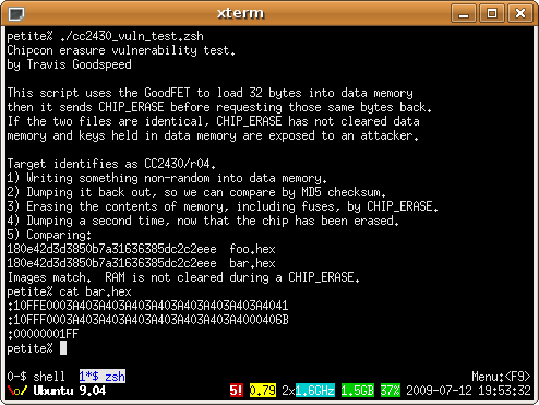
At Black Hat USA in August of 2009, I presented a paper entitled Extracting Keys from Second Generation Zigbee Chips. The vulnerability, demonstrated in the image below, is that Data memory is not cleared along with Flash memory during a CHIP_ERASE. By booting a wireless sensor, then erasing it, then dumping RAM, the attacker can find any keys which are stored within the unit. This works even for constant keys, as 8051 compilers will copy them into RAM in order to make C pointers consistent.
CC2430 Vulnerability Test

In implementing a debugger, it's also necessary to watch out for a minor bug. Upon connecting, be sure to DEBUG_INSTR a NOP so as to have the lock bit checked. Failure to do so might cause the lock bit to be misrepresented when checking the device's status.

In conclusion, the protocol is blessedly simple and the 16 pages of documentation are quite complete when supplemented with the CC2430 datasheet. I hope that these notes might allow you to implement the protocol with less of a headache than I have.

Saturday, October 3, 2009

GoodFET30 Boards by Mail

Howdy y'all,

As anyone who has taken up my offer of a free GoodFET board can tell you, I've been terribly slow at shipping the things. Not only did I only send them while I was in stock, but I also had to have ample quantities of stamps and envelopes. Further, the envelopes were often lost in the mail do to my miscalculating postage (42¢≠44¢) or failing to properly pad each board. Add my travel schedule to the mix, and it was not uncommon for a neighbor to wait more than a month for his board to arrive.

To remedy this situation, I've arranged for blank boards to be shipped from Tennessee. Presently, the new GoodFET30 boards are in stock, and I'll order more panels as soon as these run out. To order one, just send a few bucks by Paypal to <sixtysixav at hotmail.com> along with a mailing address and a note that you'd like a GoodFET30. If you're broke or religiously opposed to Paypal, just send a neighborly request to my address below and I'll see that a free board goes your way.

Assembled units are coming, but don't expect them to be available before the new year.

N.B., do not forget to include your mailing address when ordering.

Thank you kindly,
--Travis Goodspeed
<travis at radiantmachines.com>

GoodFET30